Model XP2F
Installation, Operation, and Maintenance Manual
N-XP2F IOM V1.0-4.5 Page 2 of 35
Table of Contents
1 Introduction ............................................................................................................................................................................ 3
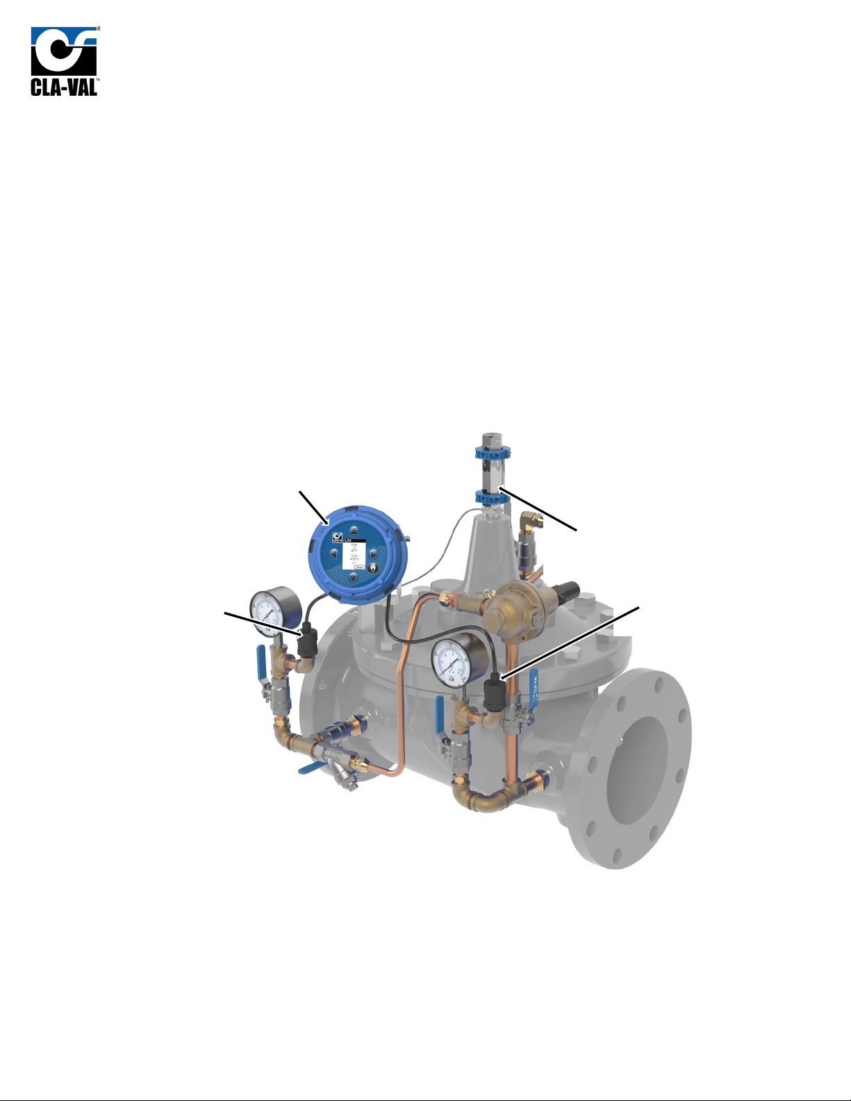
2 X117H Valve Position Transmitter........................................................................................................................................... 4
3 X141-PT Pressure Transmitters ............................................................................................................................................... 5
4 X35 Flow Calculation Module.................................................................................................................................................. 6
4.1 Installation..................................................................................................................................................................... 7
4.1.1 Valve Mounted .................................................................................................................................................... 7
4.1.2 Flat Surface Mount .............................................................................................................................................. 8
4.1.3 Installing Wire Cable Glands ................................................................................................................................ 9
4.2 Electrical Wiring........................................................................................................................................................... 10
4.2.1 Overview............................................................................................................................................................ 10
4.2.2 X35 Power Supply .............................................................................................................................................. 10
4.2.3 Analog Inputs ..................................................................................................................................................... 10
4.2.4 Analog Outputs .................................................................................................................................................. 12
4.2.5 Standard Wiring Diagram................................................................................................................................... 13
4.3 Screen Navigation........................................................................................................................................................ 14
4.4 Setup ........................................................................................................................................................................... 15
4.4.1 Initial Configuration ........................................................................................................................................... 15
4.4.2 DPM Setup ......................................................................................................................................................... 17
4.4.3 I/O Setup............................................................................................................................................................ 20
4.4.4 Calibration ......................................................................................................................................................... 22
4.4.5 Display Options .................................................................................................................................................. 23
4.4.6 Logging............................................................................................................................................................... 24
4.4.7 Date/Time .......................................................................................................................................................... 25
4.4.8 Language............................................................................................................................................................ 25
4.4.9 Factory Reset ..................................................................................................................................................... 26
4.5 SD Card Features ......................................................................................................................................................... 27
4.5.1 SD Card Removal................................................................................................................................................ 27
4.5.2 Access Logged Data............................................................................................................................................ 28
4.5.3 Firmware Update ............................................................................................................................................... 29
Appendix A: Wiring Diagram Examples........................................................................................................................................... 30
A.1 2x X141-PTs and X117H ....................................................................................................................................................... 30
A.2 DP Transmitter and X117H .................................................................................................................................................. 31
A.3 2x X141-PTs and X117D ....................................................................................................................................................... 32
A.4 DP Transmitter and X117D .................................................................................................................................................. 33
Appendix B: Full Data Acquisition Setup......................................................................................................................................... 34
B.1 Full Retransmission Wiring, 2x X141-PTs and X117H........................................................................................................... 34
B.2 Full Retransmission Device Settings..................................................................................................................................... 35