CandCNC THC Sensor PWM Instructions d'utilisation

CandCNC Page 1
This update is to cover the newer PWM rev 21, PWM Mod2 and the
soon to be released PWM II
SETTING UP THE THC SENSOR PWM MODULE
IF you already have a working PWM Module with your DTHCIV
of either REV number and you are just upgrading to the DTHC IV
for CommandCNC you can skip this section of the setup
.
PWM MODULE
REV 21 and later
THC SENSOR PWM MODULE
E
UPDATED for PWM, newerPWM MOD2
and PWM II
10/22/17

CandCNC Page 2
SETTING THE THC SENSOR PWM PRESCALE
DIVIDER RATIO( REV21)
Volts
Volts
Volts
Volts
Volts
Volts
Volts
Volts
SCALE
SCALE
SCALE
SCALE
SCALE
SCALE
SCALE
SCALE
7:1 Divider
(from CandCNC RAV-01
Card )
30:1 Divider
(Not ON Sensor PWM)
50:1 Scale (Hypertherm and
some others) Recommended
for Hypertherm with CPC
20:1 Standard on some
Thermal Dynamics, others
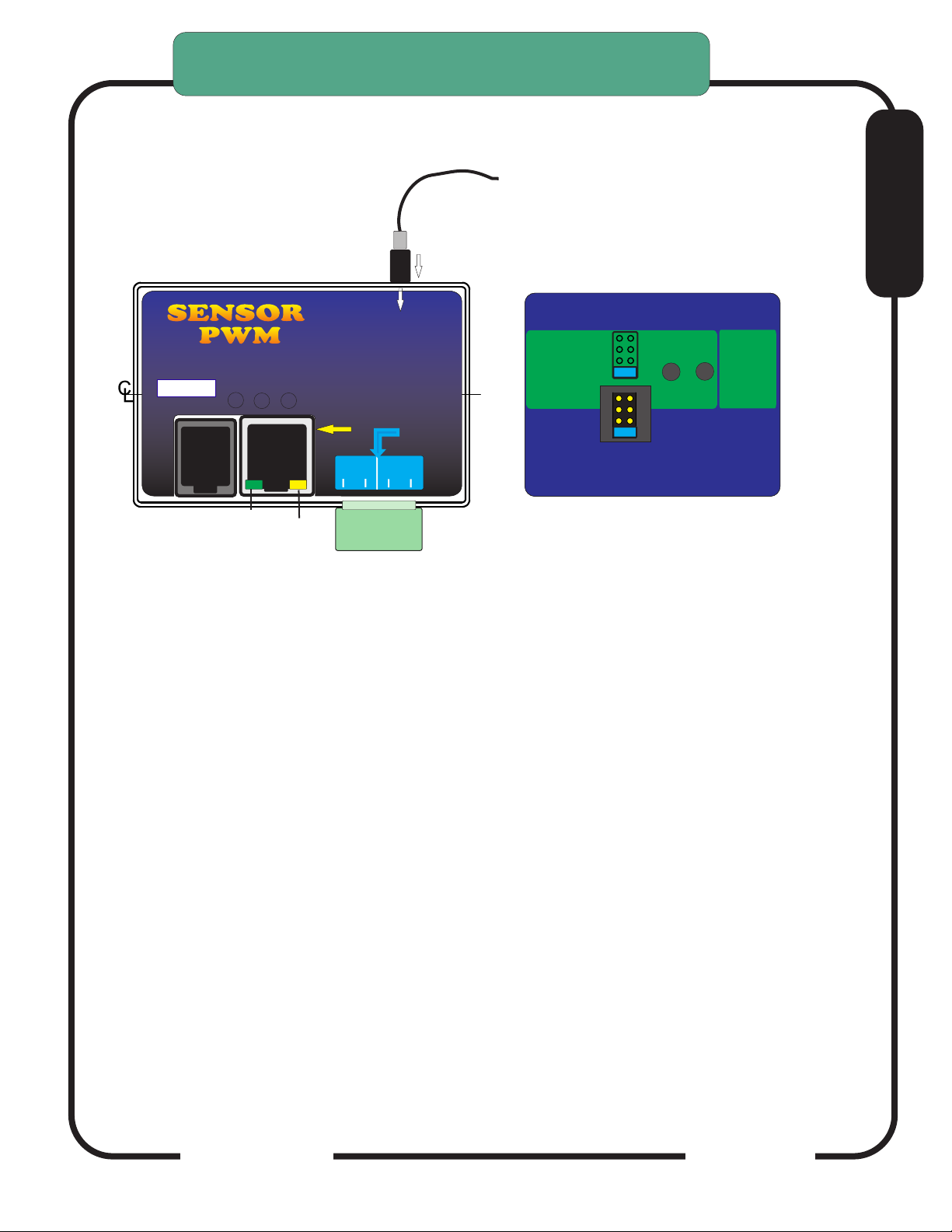
To set PWM SENSOR ratio divider option:
1. Turn case over. There is a small access slot for the
Prescale Jumpers
2. Determine the proper setting for the type setup you have.
3. Set the small option jumper to match.
7:1
7:1
7:1
7:1
7:1
20:1
20:1
20:1
20:1
20:1
50:1
50:1
50:1
50:1
50:1
N/A
30:1
THIS MUST BE DONE TO MATCH YOUR INSTALL
UNITS ARE SHIPPED TO MATCH THE RAV-01 (7:1)
RATIO. USE THE CHART BELOW IF YOU ARE USING
THE MODULE WITH A PLASMA WITH AN INTERNAL
VOLTAGE DIVIDER. SEE THE SECTION ON
CONNECTING A PLASMA WITH AN INTERNAL
VOLTAGE DIVIDER TO DETERMINE TE PROPER RATIO
IMPORTANT:
The Hypertherm 45 has an
internal voltage divider. It
cannot be changed from the
50:1 ratio. Set your PWM
Sensor jumper to the 50:1
position if you are using the
MIC-01 Direct Connect
Cable.
Rear
Prior MODEL
PWM
Shown
Remove back to access jumper
settings
DEFAULT
E
ARC
OK
VOLTS
TEST
Press and release
Volts Test. Front panel
LED Test Active
will light
Press and
Hold for
ARC OK
TEST
Check jumper settings
to match plasma divider ratio
THC Sensor PWM REV21
For use with DTHC II DTHC IV
50:1
20:1
7:1
Hypertherm
TD & Others
Not Used XX
RAV-01/02
(Factory Default)

CandCNC Page 3
CandCNC Page 4
E
Digital Plasma
Module
To DCP-01
To DTHC
Module
ARC OK
Input JACK
Divided Volts
CandCNC
Front
Arc OK
+12 PWR
To CPC or RAV-02
THC SENSOR PWM MODULE TEST/CAL
THC PWM Module (Plasma Pickup Module) can be put in TEST/CAL mode
without removing the card from the case.
Turn the case over and look on the back. There are two recessed test buttons
find the button marked VOLTS.
Unplug the Divided Volts (from the plasma) either the 2 pin plug or the stereo
plug. Leaving the Divided Volts plugged in will Skew the reading.
Push and release Volts Test, this puts the unit in test/cal mode. The yellow
Test Active on the front will flash. You should see 126 to 128 volts displayed on
the TORCH VOLTS in the CommandCNC screen
Pushing the button again will take the unit out of test/cal mode and the LED will
stop flashing and the TORCH VOLTS reading will return to Zero.
In TEST mode the PWM signal to the DTHCIV is tested. If you unit passes the
Volts Test then the Cat5 cable and DTHCIV module are operating properly. If
the voltage is still wrong or zero when the torch fires then the cable to plasma is
bad or the voltage divider in the plasma is bad.
The test is based on a simulated PWM from the circuit so if the prescale divider
setting is wrong the calibration will show correct but when the torch is fired
the voltage will be wrong.
THC SENSOR PWM MODULE VOLTS
TEST/CAL
ARC
OK
VOLTS
TEST
Press and release
Volts Test. Front panel
LED Test Active
will light
Press and
Hold for
ARC OK
TEST
Check jumper settings
to match plasma divider ratio
THC Sensor PWM REV21
For use with DTHC II DTHC IV
50:1
20:1
7:1
Hypertherm
TD & Others
Not Used XX
RAV-01/02
(Factory Default)
SENSORSENSOR
PWM PWM
Digital Plasma Module
Torch
ON
+5
To DCP-01
To DTHC
Module
Test
Active
ARC OK
To Plasma
Cable
Input JACK
Divided Volts
CandCNC
Arc OK
(Transfer)
TORCH
SWITCH
MOD 2
To Plasma

CandCNC Page 5
E
Digital Plasma
Module
Torch
Volts IN
ON
ACT
+5
To DCP-01
To DTHC
Module
Test
Active
ARC OK
To Plasma
Cable
Input JACK
Divided Volts
CandCNC
Front
Arc OK
+12 PWR
To CPC or RAV-02
THC SENSOR PWM II MODULE TEST/CAL
THC PWM II Module Rev 1.4 (Plasma Pickup Module) can be put in TEST/CAL
mode without removing the card from the case.
Turn the case over and look on the back. There are two recessed test buttons
find the button marked VOLTS.
Unplug the Divided Volts (from the plasma) either the 2 pin plug or the stereo
plug. Leaving the Divided Volts plugged in will Skew the reading.
Push and hold Volts Test puts the unit in test/cal mode. The blue Volts IN ACT
LED on the front will flash. You should see 126 to 128 volts displayed on the
TORCH VOLTS in the CommandCNC screen
Releasing the button will take the unit out of test/cal mode and the LED will stop
flashing and the TORCH VOLTS reading will return to Zero.
In TEST mode the PWM is completely tested. If you unit passes the Volts Test
but the voltage is still wrong or zero when the torch fires then the cable to
plasma is bad or the voltage divider in the plasma is bad.
The test is based on a simulated PWM from the circuit so if the prescale divider
setting is wrong the calibration will show correct but when the torch is fired
the voltage will be wrong.
THC SENSOR PWM MODULE VOLTS
TEST/CAL
Arc OK
(Transfer)
TORCH
SWITCH
SENSORSENSOR
PWM PWM
IIII ARC
OK
VOLTS
TEST
Press and HOLD
Volts Test. Front panel
blue LED Volts ACTive
will flash
Press and
Hold for
ARC OK
TEST
Check jumper settings
to match plasma divider ratio
THC Sensor PWM REV21
For use withDTHC IV DTHC V
50:1
20:1
7:1
Hypertherm
TD & Others
TD/Victor 30:1
RAV-01/02
(Factory Default)

CandCNC Page 6
CandCNC THC SENSOR
PWM and PWMII
CHECKING ARC OK SIGNAL BACK TO DTHCIV
CARD:
1. Turn case over.
2 With RJ45 (UTP cable) connected to DTHCIV and
unit powered up, depress the ARC OK TEST
BUTTON on the card. The ARC OK LED on the
MACH screen should light. The ARC OK test LED
on the front of the case will light.
Depress and Hold TEST button
to test PWM circuit back to
DTHCIV. Volts ACT LED on
front will flash and DTHC
screen in CommanCNC should
display a voltage. Calibrated
units (see DTHC calibration
section) should display 126 to
128 volts during test.
Case not shown for clearity
SENSOR
PWM
Screen may be different
THC SENSOR PWM MODULE VOLTS
TEST/CAL
ARC
OK
VOLTS
TEST
Press and HOLD
Volts Test. Front panel
blue LED Volts ACTive
will flash
Press and
Hold for
ARC OK
TEST
Check jumper settings
to match plasma divider ratio
THC Sensor PWM REV21
For use withDTHC IV DTHC V
50:1
20:1
7:1
Hypertherm
TD & Others
TD/Victor 30:1
RAV-01/02
(Factory Default)
E

CandCNC Page 7
Before you make connections to the plasma unit you may want to do some testing
to confirm proper operation of the THC SENSOR PWM with the DTHC II/ IV Module.
Connect the THC SENSOR PWM (or Sensor PWM II MODULE ) to the RJ45
(CAT5) connector on the DTHCIV Module. Be careful! Do not connect the CAT5
from the DTHCIV module to ANY OTHER RJ45 jack. It has voltages that can
damage other modules (like the USB to RS485 4 port hub or the Ethernet jack on
the controller or your PC
Start CommandCNC using the Desktop Icon Plasma Profile and make sure you
can come out of RESET and that the CP (Charge Pump) LED on the front of the
MP3600/ BladeRunner is ON.
On full controller products you have to have the Motor DC on to come out of
RESET.
Click on the TORCH icon on the screen. You should see the LED above the
TORCH button on CommandCNC turn on and there will be a click in the THC Sensor
PWM card and the small LED on the front labeled TORCH ON will light. That indicates
the TORCH ON relay is working.
The next check is to confirm the ARC OK circuit is working. Follow the instructions
for the THC SENSOR PWM section and open the back and use the ARC OK Test
button. The ARC OK LED on the MACH3 Screen should light. If it does you can
proceed to the actual hookup of the THC SENSOR PWM Module to your plasma unit.
If any of the tests fail make sure you have the cables firmly attached and that
they are the correct type.
All cards are tested at least twice and most three times before they leave the factory. It’s
unusual for a THC SENSOR PWM to be bad or fail in no load testing. If you have
checked all of the connections, cables and MACH setup and you still cannot get the THC
SENSOR to work contact us at 903-364-2740 or via e-mail at T[email protected]
NOTE: Some Larger (>100A) plasma units or older smaller models use various methods
to start the initial ARC. Most common is HF (High Frequency) start. HF Start presents
several challenges. It uses the concept that higher frequency waves travel through air
(and arc) easier than DC voltage. The HF is normally combined with a higher voltage and
it starts an ARC that the plasma uses to ignite the air. Once the arc fires, if a conductive
part is close, the arc will transfer to the material. The HF start causes a lot of noise and
current spikes. The other form of High Voltage start is the CD (Capacitor Discharge)
method. It is basically a high current version of an Automotive ignition system. Up to
30,000 volts can be generated. If the THC Sensor is not protected, the high voltage and
high frequency can cause component failure on the card or (worse) in the THC unit and
even burn the board. The THC Sensor PWM (REV18 and up) is protected from HF and
most High Voltage start circuits.
THC SENSOR PWM MODULE VOLTS
TEST/CAL
E

CandCNC Page 8
1. You need the proper CandCNC Plasma Connection Kit to make the interface to
your plasma cutter.
2. Different types of plasma cutters can be used. Some have everything needed
terminated to one connector (e.g. Hypertherm 45/65/85/105/125) with rear CPC.
Others may have the same or no external connectors. We can only cover a few
specific types.
NOTE: Some plasma cutters use a manual contact start (TAP start) when the end
of the torch has to touch the metal then be retracted to start the arc. These types
of cutters WILL NOT WORK for plasma CNC cutting.
MAKING CONNECTIONS TO
YOUR PLASMA CUTTER
A note about HF start plasma cutters and the DTHCIV.
The DTHCIV is highly isolated from the plasma side and the noise from an HF
start plasma will not enter the controlls thought the PWM module or the
DTHCIV. Most problems from HF start are from having a common
connection to the control side (motor power supply, PC or monitor, etc)
The table and plasma chassis needs a good local earth ground (rod) close to
the table. You need to separate the Plasma cutter and its cables as far as
possible from the controls. You should NOT tie the control side to the same
ground rod as the plasma or table is connected to. The AC safety grounds
between the two systems need to connect at one common point (only) and as
physically separated as possible. In severe cases you may need to provide a
separate clean ground to the control side or even place the control equipment in
a shielded metal enclosure NOT connected to the plasma ground. Even earth
grounded wires with high currents running through them will induct some noise
into anything tied to the same ground. Just a few volts of noise on a shared
ground can disrupt the operation of some PC’s. If you fire your torch and the
PC locks up , CommandCNC stops responding, or the controller does weird
things, you need to start separating the source of the noise (the plasma cutter
and the torch leads) away from the PC control side and break any LOCAL
common connections...even grounds.
E
CandCNC Page 9
MAKING CONNECTIONS TO
YOUR PLASMA CUTTER
Hooking Up Your Plasma Machine to the MP3600-DTHC IV/BladeRunnerAIO
DTHC IV LINUX
NOTE: IF you have a Hypertherm with a rear “CPC (14 pin) round connector
you can skip this section.
CAUTION: Portions of this install may include opening your plasma cutter machine and attaching wires.
MAKE SURE THE UNIT IS UNPLUGGED PRIOR TO REMOVING ANY COVER(S) OR MAKING ANY
CONNECTIONS. Plasma units have HIGH VOLTAGES present that can be dangerous or lethal. IF
YOU ARE NOT EXPERIENCED WORKING WITH HIGH VOLTAGES, DO NOT ATTEMPT TO INSTALL
THIS OR ANY OTHER DEVICE INSIDE YOUR PLASMA UNIT YOURSELF. SEEK PROFESSIONAL
HELP.
In order to control your plasma unit, there are three main connections that need to be made to the
plasma unit itself. All of the following operations are to be done with the power disconnected from your
plasma unit.
You should determine which type install you will need for your plasma.
There are 3 questions that need to be answered:
1.) Does your plasma unit have an internal ARC OK (dry contact) signal or one on a standard CPC
connector? If not then you will need to purchase and install the Digital Current Probe Option (DCP-01).
it is available separately or as part of the Universal Connection Kit
2.) Does your plasma unit have an internal voltage divider (Automation Interface) with a ratio of 20:1 or
50:1 ? If not you will need to purchase and install the Raw Arc Volts divider card (RAV-01). It is
available separately or as part of the Universal Connection Kit
3.) Are you using a hand torch or machine torch? If using a hand torch (even with a unit that is setup for
automation, you will probably need to tap into the TORCH SWITCH wires from the hand torch to fire
the torch remotely (from the computer). There is a page on how to do that from either the RAV-01 (if
you already have it because of #2 above) or directly from the THC SENSOR PWM connector.
If you have a Plasma unit that needs the RAV-02 card you will need to install that card in your plasma
unit or have it done. See the RAV-02 card section for instructions and warnings. If you are using the
DCP-01 for ARC OK, there is an addendum at the end of this manual on installing and testing the DCP-
01.
The smaller Hypertherm and other modern brand units use a low noise method called
“blowback arc start”. The electrode is mounted against a spring that keeps it pushed
against the inside of the nozzle as long as air is not flowing. When the unit is triggered the
ARC starts a few milliseconds after the current starts to flow in the electrode circuit. As the
air flows it pulls the electrode away from the nozzle and creates an ARC. That is used to
ionize the air and start the plasma.
The DTHC IV can be used with all types of plasma units. The HF units tend to be very
noisy and some even have large amounts of RFI. The total isolation of the DTHC IV circuit
from any low level (PC logic) including any common ground, stops any conducted noise.
The internal circuits are protected from RFI with proper layout and careful attention to
bypass components on all active circuits.
DTHCIV1-14_2
E

CandCNC Page 10
1. Most plasma units have connection terminals where wires from the torch or panel connectors
attach to the internal PC Boards. The terminals provide a convenient place to do your connections.
Use crimp-on spade or round terminals to attach the wires to the terminal strips. Make sure the new
wires you install do not touch adjacent metal objects. On some machines there may be more than
one set of small wires and are used for sensing tip shorts and other conditions. To identity the
correct pair for the Torch Switch use an ohmmeter or continuity checker across each pair while
you manually push the torch head button. When you identify the pair make note of where they
attach. Use #22 to #18 stranded wire (twisted pair) to connect between the two screw terminals on
the THC Sensor PCB marked “Torch Switch” to the two switch terminals in the plasma unit.
There is no polarity. NOTE: IF your unit has noise filter chokes from the
torch switch wires up to its internal logic card, it is recommended you place
the two wires to the RAV-02 PCB on the other side of the chokes from
their torch head connection (end closest to the internal logic card).
2. If your unit has a Raw Arc Voltage connection point (i.e. like the Hypertherm
1000 series), you will need to use their manual and suggestions as to how
to connect to the two points and run those wires to the RAV-02 card.
Just make sure you use wire that has insulation rated for at least 400 V.
Small signal wire like telephone wire (UTP) is not rated that high and can
arc to nearby components. The RAV-02 card is designed to take the
full tip voltage and divide and filter it. Open circuit full tip voltage can be
as high as 300VDC in some machines.
3. If your plasma unit does not have a designated tip voltage measurement point, you will
need to locate a place inside the unit where
you can get one wire onto the WORK CLAMP lead and another on the heavy
lead(s) that connects to the torch tip (ELECTRODE).
a. Note: some machines like the Hypertherm 380 do not have a single
heavy wire to the Torch tip and instead have a set of parallel smaller
wires that all terminate into one connector. In the case of the 380 the
WHITE wires are the tip volts negative.
b. You can identify both locations by visually tracing the two leads as
they come into the box. You should find several locations/terminal strips that have connections to
these two points and you can use those for your sense wire connections. Use unshielded stranded.
c. Make a connection between the locations you have identified that tie directly to the two
leads (workclamp and torch tip) to the two “TIP Volts” terminals. Make sure that these wires are
routed where they cannot come into contact with hot or moving components. The TIP VOLTS inputs
on the RAV-02 card have a polarity. The + side is the Workclamp and the - side is the Electrode
SELECT PLASMA CONNECTION KIT
NOTE: IF you have a Hypertherm or Thermal Dynamcis “A”
series with a rear “CPC (14 pin) round connector you can skip
this section.
E
Table des matières
Autres manuels CandCNC Unité de contrôle

Manuels Unité de contrôle populaires d'autres marques

Festo
Festo Compact Performance CP-FB6-E Manuel de la liste des pièces

Elo TouchSystems
Elo TouchSystems DMS-SA19P-EXTME Manuel utilisateur

JS Automation
JS Automation MPC3034A Manuel utilisateur

JAUDT
JAUDT SW GII 6406 Series Guide rapide

Spektrum
Spektrum Air Module System Manuel utilisateur

BOC Edwards
BOC Edwards Q Series Manuel utilisateur


