Bitzer CM-RC-01 Caractéristiques techniques

KW-231-1
Instructions for mounting the CM-RC-01 add-on kit
Translation of the original document
English....................................................................................................................................................... 2
Anleitung zur Montage des CM-RC-01 Komplettierungsbausatzes
Originaldokument
Deutsch ..................................................................................................................................................... 20
4JE-13Y .. 4FE-35(Y)
6JE-22Y .. 6FE-50(Y)

KW-231-12
Table of contents
1 Introduction............................................................................................................................................................3
2 Safety ....................................................................................................................................................................3
2.1 Also observe the following technical documents ...........................................................................................3
2.2 Authorized staff..............................................................................................................................................3
2.3 Residual risks ................................................................................................................................................3
2.4 Safety references...........................................................................................................................................3
2.4.1 General safety references.................................................................................................................. 3
3 Mounting the CM-RC-01 basic kit..........................................................................................................................4
3.1 Mounting the cable holders............................................................................................................................5
3.2 Removing the SE-B* motor protection device ...............................................................................................5
3.3 Oil heater .......................................................................................................................................................7
3.4 Mounting the discharge gas temperature sensor ..........................................................................................7
3.5 Mounting the DP1 oil monitoring device ........................................................................................................8
3.6 Further electrical connections on the CM-RC-01...........................................................................................9
3.7 Laying the cables...........................................................................................................................................9
3.8 Screwing the cover onto the module housing..............................................................................................10
4 Mounting the optional CM-RC-01 extension kits .................................................................................................10
4.1 Mounting the extension kit "Capacity control" (CRII) and "Start unloading" (SU)........................................11
4.2 Mounting the "Pressure transmitter" extension kit .......................................................................................12
4.3 Mounting the "Liquid injection" extension kit................................................................................................13
4.4 Mounting the "Additional fan" extension kit..................................................................................................16
5 Communication via BEST SOFTWARE ..............................................................................................................18
5.1 Configuration via BEST SOFTWARE ..........................................................................................................19

KW-231-1 3
1 Introduction
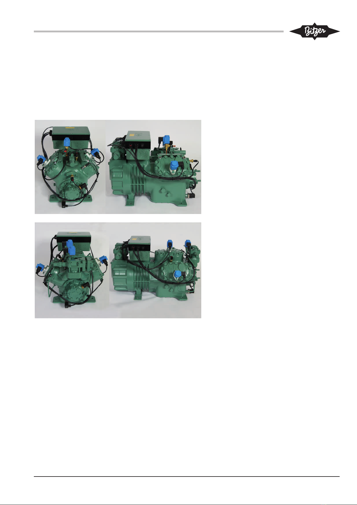
This document describes the procedure to follow for
mounting the CM-RC-01 compressor module add-on kit
to the compressor models 4JE-13Y .. 4FE-35(Y) and
6JE-22Y .. 6FE-50(Y). The description explains how to
subsequently mount any component of the basic kit
and the optional extension kits to the compressor. For
electrical connection, please refer to the Technical In-
formation KT-230 enclosed.
Information
Observe the tightening torques for screwed con-
nections (see also Maintenance Instructions
KW-100)!
2 Safety
Compressor and compressor module have been built in
accordance with state-of-the-art technology and current
regulations. Particular importance has been placed on
user safety.
The notes given in the Operating Instructions for the
compressor must be followed in addition to these Main-
tenance Instructions.
Always keep the Operating Instructions and these
Maintenance Instructions in the vicinity of the refrigera-
tion system during the whole lifetime of the com-
pressor!
2.1 Also observe the following technical documents
Number Topic
KB-104 Operating Instructions ECOLINE com-
pressors
KT-150 Oil heater
KW-100 Tightening torques for screwed connec-
tions
KT-230 Compressor module CM-RC-01
2.2 Authorized staff
All work done on the compressors, the refrigeration
systems and their electronic accessories may only be
performed by qualified and authorized personnel who
have been trained and instructed accordingly. The local
regulations and guidelines will apply with respect to the
qualification and expertise of the specialists.
2.3 Residual risks
Compressors and electronic accessories may present
unavoidable residual risks. This is why any person
working on this device must carefully read this docu-
ment!
The following regulations shall apply:
• the relevant safety regulations and standards (e.g.
EN378, EN60204 and EN60335),
• generally accepted safety rules,
• EU directives,
• national regulations.
2.4 Safety references
are instructions intended to prevent hazards. Safety ref-
erences must be stringently observed!
!
!
NOTICE
Safety reference to avoid situations which may
result in damage to a device or its equipment.
CAUTION
Safety reference to avoid a potentially hazard-
ous situation which may result in minor or mod-
erate injury.
WARNING
Safety reference to avoid a potentially hazard-
ous situation which could result in death or seri-
ous injury.
DANGER
Safety reference to avoid an imminently hazard-
ous situation which may result in death or seri-
ous injury.
2.4.1 General safety references
To be observed when performing work on the
compressor
WARNING
The compressor is under pressure!
Serious injuries are possible.
Depressurize the compressor!
Wear safety goggles!

KW-231-14
When working on the electrical and/or electronic
system, please observe the following
WARNING
Risk of electric shock!
Before working on the terminal box, module
housing and electrical lines: Switch off the main
switch and secure it against being switched on
again!
Close the terminal box and the module housing
before switching on again!
!
!
NOTICE
The compressor module may be damaged or
fail!
Never apply any voltage to the terminals of CN7
to CN12 – not even for test purposes!
The voltage applied to the terminals of CN13
must not exceed 10V!
The voltage applied to terminal 3 of CN14 must
not exceed 24V! Do no apply voltage to the
other terminals!
Never apply voltage to the voltage outputs, not even for
testing.
3 Mounting the CM-RC-01 basic kit
Procedure to follow for mounting the CM-RC-01 basic
kit of the compressor module add-on kit:
• Mounting the cable holders and cable ties.
• Removing the SE-B* protection device.
• Electrical connection of the oil heater to the com-
pressor module.
• Mounting the discharge gas temperature sensor.
• Mounting the oil monitoring device.
• Laying the cables and closing the cable ties.
• Closing the cover, screwing the compressor module
to the terminal box.

KW-231-1 5
3.1 Mounting the cable holders
4JE-13Y .. 6FE-50(Y):
Mount 2 cable holders each to the outer cylinder
heads and to the bearing cover.
• To this end, loosen the corresponding screws
on cylinder head and bearing cover, insert the
screws again with cable holders and tighten
them (tightening torque 80 Nm).
• Fasten the plastic clip to the cable holder and
insert a cable tie.
3.2 Removing the SE-B* motor protection device
• Loosen the screws on the cover of the com-
pressor's terminal box and remove the cover.
• Then unscrew the protective earth conductor
from the terminal box cover.

KW-231-16
Dismount the SE-B* motor protection device
from the terminal box.
• Pull the orange motor PTC cable off the ter-
minal plate.
• Then loosen the fixing screws of the motor
protection device and remove the device.
• Put the CM-RC-01 compressor module onto
the terminal box.
• Guide the orange motor PTC cable of the
compressor module downward through the
opening in the module housing and connect it
to the terminal plate of the compressor.
• Then guide the protective earth conductor of
the compressor upward into the module hous-
ing through the opening provided in the hous-
ing.
• Properly position the compressor module on
the terminal box. The long side that is
provided with the numerous cable bushings of
the compressor module must point in the dir-
ection of the suction gas valve.
• Screw the protective earth conductor onto the
module housing.

KW-231-1 7
3.3 Oil heater
• Loosen and remove the connector and cable
of the installed oil heater.
• Then plug the electric connector with its cable
(labelled "Crankcase Heater") prewired to ter-
minal strip CN4, with a seal onto the oil heater
and tighten it (tightening torque 5 Nm).
Information
For oil heater mounting, see Technical
Information KT-150.
3.4 Mounting the discharge gas temperature sensor
After mounting new components such as discharge gas
temperature sensor, injection nozzle or injection valve:
!
!
NOTICE
Serious injuries are possible. New component
may suddenly become detached.
Check the thread.
Carefully screw in the new component. Observe
the tightening torques!
Perform a tightness test before commissioning!
Information
Observe the different connection positions of
the discharge gas temperature sensor on 4-cyl-
inder and 6-cylinder compressors!
4-cylinder compressors 4JE-13Y .. 4FE-35(Y):
• Remove the sealing plug from the connector
marked by a circle and clean the threaded
bore.
• Then screw the discharge gas temperature
sensor in (tightening torque 35-40 Nm) and
tighten the connector by hand.
• Guide the cable of the discharge gas temper-
ature sensor to the compressor module as
shown in the figure.

KW-231-18
6-cylinder compressors 6JE-22Y .. 6FE-50(Y):
• Remove the sealing plug from the connector
marked by a circle and clean the threaded
bore.
• Then screw the discharge gas temperature
sensor in (tightening torque 35-40 Nm) and
tighten the connector by hand.
• Guide the cable of the discharge gas temper-
ature sensor to the compressor module as
shown in the figure.
3.5 Mounting the DP1 oil monitoring device
• Unscrew the plug or an existing oil sensor
from the bearing cover and clean the
threaded bore.
• Screw the oil monitoring device with O-ring
and metal gasket into the bearing cover (tight-
ening torque 75 Nm). Carefully mount the O-
ring!
• Connect the cable clip to the DP1 sensor in-
dependently of the polarity.
• Attach the connection cap and tighten the
screw (position and downward cable routing,
see figure).
Next, any optional extension kits can be moun-
ted see chapter Mounting the optional CM-
RC-01 extension kits, page 10).

KW-231-1 9
3.6 Further electrical connections on the CM-RC-01
• Voltage supply of the compressor module on ter-
minal strip CN1 (115 .. 230V +10%/-15%, 50/60Hz)
– Terminal 1: L
– Terminal 2: N
• Command for compressor start (release signal from
system controller).
• Analogue signal for capacity control from the system
controller (0 .. 10 V).
Schematic wiring diagram and further information, see
Technical Information KT-230.
3.7 Laying the cables
4-cylinder compressors 4JE-13Y .. 4FE-35(Y):
• Lay the cables along the cable holders and
use cable ties to fix them.
The figure shows the compressor with compon-
ents of the optional extension kits.
6-cylinder compressors 6JE-22Y .. 6FE-50(Y):
• Lay the cables along the cable holders and
use cable ties to fix them.
The figure shows the compressor with compon-
ents of the optional extension kits.

KW-231-110
3.8 Screwing the cover onto the module housing
• Attach the enclosed adhesive label "CM-
RC-01" into the cover of the terminal box.
• Then screw the protective earth conductor to
the terminal box cover.
• Put the terminal box cover on the compressor
module housing and fasten it using the 6 en-
closed screws (M5 x 70 mm).
4 Mounting the optional CM-RC-01 extension kits
Required components and procedure to follow for
mounting the optional extension kits of the compressor
module add-on kit:
• Mounting and connecting valve flanges and solenoid
valves for capacity control (CRII) and/or start unload-
ing (SU).
• Mounting and connecting the pressure transmitters.
• Mounting and connecting the liquid injection.
• Mounting and connecting the additional fan.
WARNING
The compressor is under pressure!
Serious injuries are possible.
Depressurize the compressor!
Wear safety goggles!
After mounting new components such as discharge gas
temperature sensor, injection nozzle or injection valve:
Autres manuels pour CM-RC-01
6
Table des matières
Langues :
Autres manuels Bitzer Unité de contrôle
Manuels Unité de contrôle populaires d'autres marques

Festo
Festo Compact Performance CP-FB6-E Manuel de la liste des pièces

Elo TouchSystems
Elo TouchSystems DMS-SA19P-EXTME Manuel utilisateur

JS Automation
JS Automation MPC3034A Manuel utilisateur

JAUDT
JAUDT SW GII 6406 Series Guide rapide

Spektrum
Spektrum Air Module System Manuel utilisateur

BOC Edwards
BOC Edwards Q Series Manuel utilisateur


