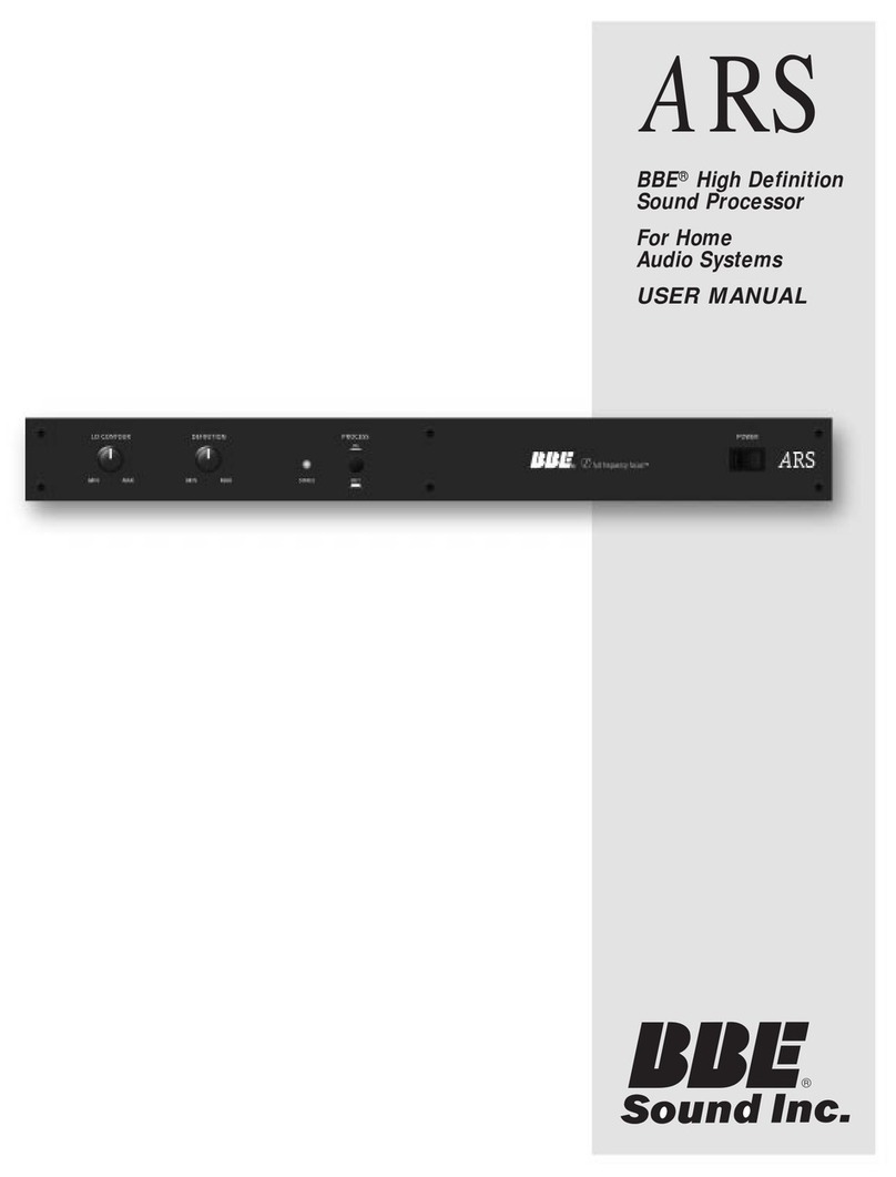
BBE DS24 Manuel utilisateur

DIGITAL SPEAKER PROCESSOR
DS24/DS26
•User Guide
•Reference Manual
professional products

i
IMPORTANT SAFEGUARDS
®

ii
CONTENTS
DS24/DS26 and DS26 Features ……………………………………………………v
1 Introduction ……………………………………………………………………vi
2 What is a Speaker Management System? ……………………………………1
2.1 Crossover: ……………………………………………………………………1
2.2 Equalization: …………………………………………………………………1
2.3 Delay: ………………………………………………………………………1
2.4 High Pass and Low Pass Filters: …………………………………………1
2.5 Limiting: ………………………………………………………………………1
3 Front Panel ………………………………………………………………………2
4 Rear Panel ………………………………………………………………………3
5 Quickstart ………………………………………………………………………4
6 Installation ………………………………………………………………………6
6.1 RACK MOUNTING …………………………………………………………6
6.2 CONNECTORS ………………………………………………………………6
7 OPERATION ………………………………………………………………………7
7.1 Navigating Front Panel Controls……………………………………………7
7.1.1 Hints for Operation: ………………………………………………7
7.2 SUBMENUS …………………………………………………………………8
7.2.1.1 Crossover Submenu ……………………………………………8
7.2.1.2 Load a Xover: ……………………………………………………8
7.2.1.3 Design a Xover; …………………………………………………8
7.2.1.4 Store a Xover: ……………………………………………………8
7.2.1.5 Erase a Xover:……………………………………………………8
7.3 Security Submenu……………………………………………………………8
7.4 Subsystem Submenu ………………………………………………………9
7.5 Interface Submenu …………………………………………………………10
7.6 Parameter……………………………………………………………………10
7.6.1 Gain: ………………………………………………………………10
7.6.1.1Inputs: ……………………………………………………………10
7.6.1.2Outputs: …………………………………………………………10
7.6.1.3Polarity: …………………………………………………………11
7.6.1.4 Delay: ……………………………………………………………11
7.6.1.5 HPF: ……………………………………………………………11
7.6.1.6 LPF:………………………………………………………………11
7.6.1.7 PEQ: ……………………………………………………………12
7.6.1.8 Limiter: …………………………………………………………12
7.6.1.9 Name of channel: ………………………………………………13
7.6.1.10 Input Signal:……………………………………………………13
7.7 DS26 BLOCK DIAGRAM …………………………………………………14
7.8 DS24 BLOCK DIAGRAM …………………………………………………16
8 Graphical User Interface (GUI)…………………………………………………17
8.1 MINIMUM SYSTEM REQUIREMENTS …………………………………17
8.2 INSTALLING SYSOMAX ON YOUR COMPUTER ……………………17
Jump ahead to
quick start

8.3 STARTING UP SYSOMAX ………………………………………………18
8.3.1 From the Start menu: ……………………………………………18
8.3.2 From Windows Explorer or My Computer: ……………………18
8.4 Navigating SYSOMAX ……………………………………………………18
8.4.1 Crossover Types DS24 …………………………………………19
8.4.2 Crossover Types DS26 …………………………………………19
8.4.3 Top Line Menu……………………………………………………20
9 Creating a Program………………………………………………………………22
9.1 GAINS: ……………………………………………………………………22
9.2 DELAYS: ……………………………………………………………………22
9.3 LIMITERS: …………………………………………………………………22
9.4 OUT 1, OUT 2, etc. ………………………………………………………23
9.5 Crossover Filters: …………………………………………………………23
9.6 Parametric Equalizers: ……………………………………………………23
10 SPECIFICATIONS ………………………………………………………………25
11 Service ……………………………………………………………………26
12 Warranty ……………………………………………………………………26
13 Maintenance ……………………………………………………………………27
iii
CONTENTS
®
IMPORTANT !BEFORE YOU BEGIN, PLEASE CHECK THE CONTENTS WITHIN
THIS BOX TO INSURE THESE ITEMS ARE INCLUDED:
1. The BBE DS24/DS26 or DS26 Digital Speaker Processor.
2. The BBE DS24/DS26/DS26 Digital Speaker Processor User’s Manual.
3. Power cord.
4. Warranty registration card.
5. Software Disc
6. DB-9 type serial cable for connection between unit and PC.
If any of these items are found to be damaged or missing, immediately contact
the BBE dealer you purchased it from. This manual will help you to effectively
utilize the BBE DS24/26. Reviewing the information contained in this manual
will answer most of the common questions that our service department
receives. If you still have questions, please feel free to call 800-233-8346.

iv
DS24/DS26 AND DS26 FEATURES
• Choice of 2 X2-way, 2 X 3-way, 2-way + sub, 4-way, 5-way 6-way
crossover (depending on model)
• DS24 is 2 inputs 4 outputs and includes 4 crossover configurations
• DS26 is 2 inputs 6 outputs and includes 6 crossover configurations
• Input gain control for each channel
• Separate crossover controller
• 5 band fully parametric equalizer
• Driver Alignment Delay for each output up to 7ms
• Output gain and phase control
• Security lockout to discourage system tampering
• RS-232 remote control PC interface
(Windows compatible software included)
• Each group parametric equalizer has 31 ISO frequencies
with + or - 12dB gain
• Each group Q value is from 0.5 to 10 and provides Hi shelf
• Lo shelf selects function.
• Separate limiter with Attack, Hold, Decay and Threshold parameters
• High Pass and Low Pass filter available for each channel
@ 6 or 12dB slope
• Choice of 18dB, 24dB, 48dB Butterworth, Linkwitz-Riley or Bessel
frequency response curve
• Memory for up to 10 on-board user programs
• 8X7 bit input/output precision digital LED meter.
• 2X20LCD backlit. LED Display
Crossovers
Parametric
Equalizers
Driver
Alignment
Delay
Speaker
Protection
limiter
10 user
memories

v
INTRODUCTION
®
Thank you for choosing the BBE DS24/DS26 Speaker Management System.
This product will enable you to obtain the best possible performance from
your loudspeaker system. You can also reduce the amount of outboard gear
that is required to transport, set-up and operate as part of the sound system.
The DS24/DS26 offers many powerful functions. It is highly recommended
that you read through this manual before you begin connection and operation.
For those that are familiar with this type of device or if you simply can't wait
to hear how good your system will sound, a Quick Start section follows on
pages 4-5.
SOME TERMS THAT WILL BE USED IN THIS MANUAL:
Configuration: This refers to a particular group of settings, with
the primary parameter being the crossover type.
Program: A program is a configuration with either the factory
default or a user-created name.
Configuration and Program may be used interchangeably, though
a configuration must be programmed for a program to exist.
Parameter: A component of a setting such as the center frequen-
cy of one band of parametric EQ or the attack time of a limiter.
WARNING!
To prevent possible speaker or
amplifier damage, always power-up peripheral
devices first, wait 10 seconds, and then turn on the
power amplifier. Turn off power amplifier first, then
power-down peripheral devices.

1
WHAT IS A SPEAKER MANAGEMENT SYSTEM?
A Speaker Management System uses digital signal processing to accom-
plish multiple functions that affect the audio signal between the mixer and
the power amplifiers. These functions include crossover, equalization,
delay, limiting, high-pass and low-pass filtering as well as signal distribu-
tion. Programs may be created, selected and edited with the DS24/DS26's
front panel controls. However, to create new programs, it is best to use the
included free PC software and configure the programs using the graphical
user interface (GUI) and a Windows PC.
2.1 Crossover:
This function used filters to divide the audio spectrum into multiple bands, such as Highs,
Mids, and Lows. When these separate signals are individually amplified and sent to a
speaker matched for that range, the result is a much more efficient system with more
punch and clarity as compared to system using a two or three-way speaker box with a
passive cross-over. The common terms used for two or three-way systems are "bi-amp"
and "tri-amp".
2.2 Equalization:
This function provides control of the tonal spectrum. It can be used to compensate for dif-
fering acoustic conditions, speaker cabinet responses or boosting/cutting certain frequen-
cy ranges to create a specific type of sound. In some rooms, "ringing" or feedback is
present due to a number of conditions. Use the PEQ function to reduce the ringing fre-
quencies.
2.3 Delay:
This function is used to "time-align" the different transducers in a speaker system. A
properly aligned system will have better phase coherence resulting in more focused
sound.
2.4 High Pass and Low Pass Filters:
These are used to reduce any signal outside of the desired bandwidth and are part of the
equalization function. This frees the power amps and speakers from trying to reproduce
signals that are not an intended part of the mix or simply beyond the reproduction range
of the loudspeakers.
2.5 Limiting:
This function prevents a signal from exceeding a certain pre-determined level. It prevents
input overload with its resultant distortion and also keeps amplifiers from clipping, which
protects the speakers.

2
FRONT PANEL
®
1. LCD
The 2x20 backlit LCD displays the program and programming choices of the unit.
2. <Back/Next>
These buttons allow navigation for selection of sub-menus and some parameter values.
3. Menu
This is one of two buttons that will access the front panel programming. This one is used
primarily to select which program to call up, edit or save.
4. Gain
This is one of two buttons that will access the front panel programming. This, along with
the <Back/Next> buttons, accesses the various parameters of a program.
5. Quit
This exits the programming menu and returns the display to showing the selected pro-
gram.
6. Enter
Hitting this button will write the current selection to memory.
7. Param
This acts as the value selection dial when selecting certain parameters or values for cer-
tain parameters (such as Gain). It is both a dial and a button. DO NOT PRESS IN WHEN
ROTATING OR THE VALUES MAY NOT TRACK CORRECTLY.
8. Meters
These display the respective input and output levels of the device. The seven LED seg-
ments per display are in 6 dB steps from –30dbV to –6dBV, then -3dBV, then Limit (0dBV),
then Clip (+8 dBV)
9. Mute
Pressing one of these buttons will mute the respective Output channel and the LED will
illuminate. All outputs will mute automatically during certain program selection and edit-
ing processes, to protect the loudspeakers.
10. Power
This turns the power to the unit On and Off. Remember to always turn power amps on last
after everything else and turn them off first, before everything else.

3
REAR PANEL
1. Power Jack
This accepts a standard IEC type AC bayonet plug.
2. RS232 Interface
Connect this to the serial port on a PC using the included cable or other standard DB-9
type cable. With the software installed, the PC can now monitor and program the
DS24/DS26.
3. XLR Input
These are balanced (Pin 2 Hot) XLR inputs that accept the signal from the (usually main)
outputs of the mixer.
4. XLR Output
These are balanced (Pin 2 Hot) XLR outputs. Depending on the model, there will either be
4 or 6 outputs.

4
QUICK START
®
NOTE: This section will describe navigation of the front panel controls as follows:
The button to press will be shown in ALL CAPITALS. For QUICK START, a number following in
parentheses (#) will also be included. These refer to the same names and numbers as shown
in Figure 1, Front Panel Controls and Indicators. The expected display text is shown in "quo-
tation marks". If you press a button and the display does not change, it means that the but-
ton has no effect for that particular menu item.
If you get to a certain point in the menu and want to go back, but cannot, press QUIT (5) and
begin the steps again. This is normal for the unit.
1. Before hooking up the system, make sure that all items are OFF, especially the power amps.
2. Use high quality balanced XLR mic cables to make the connections. The feeds from the DS24/DS26 at "front
of house" can also be sent through the audio snake returns to the amp stacks if used in a live setting.
3. You should know the frequency response and limits of your loudspeakers
4. Connect the main output or outputs of your mixer to the inputs of the DS24/DS26.
5. Depending on the configuration you select, connect the appropriate number of outputs from the DS24/DS26
to your power amp inputs.
6. Turn on the DS24/DS26.
7. After a brief start up, the display will show "2 x 2 WAY X-OVER"
8. Press MENU (3).
Press ENTER (6).
Press NEXT (2) "Design a Xover"
9. Press ENTER (6).
Select the crossover mode desired with either the BACK/NEXT (2) buttons or the Parameter dial. After selec-
tion, Press ENTER (6).
Ce manuel convient aux modèles suivants
1
Table des matières
Autres manuels BBE Matériel informatique
Manuels Matériel informatique populaires d'autres marques

EMC2
EMC2 VNX Series Manuel du propriétaire

Panasonic
Panasonic DV0PM20105 Manuel utilisateur

Mitsubishi Electric
Mitsubishi Electric Q81BD-J61BT11 Manuel utilisateur

Gigabyte
Gigabyte B660M DS3H AX DDR4 Manuel utilisateur

Raidon
Raidon iT2300 Manuel utilisateur

National Instruments
National Instruments PXI-8186 Manuel utilisateur