baxter ML-132580 Manuel utilisateur

Baxter Mfg, a Division of ITW FEG, LLC • 19220 State Route 162 East • Orting, WA 98360-9236
Phone: (360) 893-5554 • Fax: (360) 893-1337
www.baxtermfg.com
Model Number: ___________
Serial Number: ___________
Date of Installation: ___________
Operator & Installation
Manual
WATER METERS
WM600 ML-132580
WM600C ML-132580
FORM 36817 Rev. B (October 2022)

– 2 –
©BAXTER MFG, 2022
TABLE OF CONTENTS
GENERAL............................................................................................................................................. 3
INSTALLATION.................................................................................................................................... 4
Unpacking........................................................................................................................................ 4
Location ........................................................................................................................................... 4
Wall Mounting .................................................................................................................................. 4
Installation Codes and Standards.................................................................................................... 5
Electrical Connections ..................................................................................................................... 5
Water Supply ................................................................................................................................... 7
Drain Connections ........................................................................................................................... 7
Plumbing Connections..................................................................................................................... 8
Assembly ....................................................................................................................................... 10
Setting Water Pressure.................................................................................................................. 10
OPERATION .......................................................................................................................................11
Environmental Conditions...............................................................................................................11
Controls ..........................................................................................................................................11
Before First Use............................................................................................................................. 13
Using the WM600/WM600C Water Meter ..................................................................................... 14
Using the Temperature Probe........................................................................................................ 15
Flush Time ..................................................................................................................................... 16
Shutdown....................................................................................................................................... 16
CLEANING ......................................................................................................................................... 17
MAINTENANCE................................................................................................................................. 18
Service and Parts Information ....................................................................................................... 18
Calibration Check .......................................................................................................................... 18
Operating Parameter Setup........................................................................................................... 22
TROUBLESHOOTING ...................................................................................................................... 24

– 3 –
INSTALLATION, OPERATION AND CARE OF
BAXTER MODEL WM600 & WM600C WATER METER
SAVE THESE INSTRUCTIONS
GENERAL
The WM600 & WM600C Water Meter is a microcomputer-controlled water delivery system that enables
you to accurately control the water requirements for your baking needs. Through the proper control of
water temperature and volume, the water meter will help you gain uniform baking results and maximum
productivity.
Baxter Water Meters are produced with quality workmanship and material. Proper installation, usage and
maintenance of your water meter will result in many years of satisfactory performance.
It is suggested that you thoroughly read this entire manual and carefully follow all of the instructions provided.

– 4 –
INSTALLATION
The water meter requires separate hot and cold supply lines. Each line should have a manual shuto valve
(not supplied) at the water meter for servicing and shutdown. Before installing, verify that the electrical
service agrees with the specications on the data plate located on the left panel of the water meter. If the
supply and equipment requirements do not agree, do not proceed with the installation. Contact your local
authorized service oce immediately.
UNPACKING
This water meter was inspected before leaving the factory. The transportation company assumes full
responsibility for safe delivery upon acceptance of the shipment. Immediately after unpacking, check for
possible shipping damage. If the water meter is found to be damaged, save the packaging material and
contact the carrier within 15 days of delivery.
LOCATION
Before nalizing location, make sure that consideration has been given for water supply, draining, electrical
outlets and service clearances.
WALL MOUNTING
The water meter has a detachable base for wall mounting. It is secured by a machine screw located on
the bottom panel.
1. With the water meter lying at, control face up, remove the machine screw and angle holddown.
2. Slide the water meter forward and set aside.
3. Position the base on the wall and level left-to-right using a carpenter’s level.
4. Mark the position and hole location.
5. Mount the base to the wall using the appropriate mounting fasteners.
6. Slide the water meter, with the control panel facing up, downward onto the base. Make sure the
horizontal groove on the back of the water meter is lined up with the top edge of the base.
7. Secure water meter to the base with the machine screw and angle holddown.
8. Check to make sure the water meter is level.

– 5 –
INSTALLATION CODES AND STANDARDS
The water meter must be installed in accordance with:
In the United States of America:
1. State and local codes.
2. National Electrical Code, ANSI/NFPA-70 (latest edition). Copies may be obtained from The National
Fire Protection Association, Batterymarch Park, Quincy, MA 02169.
In Canada:
1. Local codes.
2. Canadian Electric Code, CSA C22.1 (latest edition). Copies may be obtained from The Canadian
StandardAssociation, 178 Rexdale Blvd., Etobicoke, Ontario, Canada M9W 1R3. (electric equipment)
In Europe:
1. Local codes.
ELECTRICAL CONNECTIONS
Electrical and grounding connections must comply with the applicable portions of
the national electrical code and/or other local electrical codes.
Appliances equipped with a exible electric supply cord are provided with a
three-prong grounding plug. This plug must be connected into a properly grounded three-prong
receptacle. If the receptacle is not the proper grounding type, contact an electrician. Do not remove
the grounding prong from this plug.
Electrical data is located on the left panel as you face the water meter. Route the power cord safely out
of the way of other equipment, personnel and moisture.
If the equipment is used in a manner not specied by the manufacturer, the protection provided by the
equipment may be impaired.
Model
Electrical Option
US Europe Auxiliary Relay Rating
WM600 WM600C
Volts 120 230/250 120/240
Hertz 60 50/60 Single Phase
Amp 0.5 1.4/1.3 7 Max.

– 6 –
Units with 120VAC Power Supply
• Replace any UL listed fast-acting 0.5A/250VAC
fuse inside the water meter if fuse is blown.
Units with 230VAC/250VAC Power Supply
• For 230VAC/250VAC operation, replace any
UL listed fast-acting 3A/600V fuse inside the
junction box if fuse is blown.
Input power line and branch circuit protection will be
provided and wired by customer. Refer to Fig. 1 for
240V junction box wiring diagram.
NOTE: It is recommended that a switch or circuit breaker
(marked as the connecting device) is located near the
equipment and within easy reach of the operator.
Fig. 2
Fig. 1
Water Chiller Option
If water chiller is pump-driven, connect the chiller to the water meter as described in the steps below.
Connection to the water chiller circuit should be done by a qualied electrician or service technician. The
auxiliary switch is located in the top-mounted junction box.
Disconnect the electrical power to the machine and follow lockout / tagout
procedures.
1. Verify that the water chiller circuit does not exceed the
auxiliary relay rating.
2. Remove the junction box cover screws, cover and gasket.
3. Connect water chiller and meter per Fig. 2.
4. Install the junction box gasket and cover. Secure with
the previously removed junction box screws.
5. Connect power to the meter. While test is owing, verify
that the water chiller pump motor is running in the proper
direction.

– 7 –
WATER SUPPLY
The water meter requires separate hot and cold supply lines. A manual shuto valve (not supplied) should
be installed on each supply line at the water meter to accommodate servicing and shutdown.
• HOT WATER INLET TEMPERATURE: 140°F (60°C) recommended.
• HOT AND COLD WATER FLOWING PRESSURE: 30 psi (207 kPa) minimum.
• WATER HARDNESS: 4 to 6 grains per gallon (0.7 to 1.0 grains per liter) is recommended.
DRAIN CONNECTIONS (FIG. 3)
The water meter should be located near a sink for the bypass line to drain into while test owing or when
water is adjusting to a set temperature.
For water meters equipped with a water chiller and with a water reservoir, a bypass return line should be
connected back to the water chiller reservoir.
WATER METER AND HAND SINK SETUP
NOTE: The hot and cold water supply lines can vary in location.
Fig. 3
– 8 –
PLUMBING CONNECTIONS
Water and waste piping and connections shall comply with the International Plumbing Code 2003,
International Code Council (ICC), or to the Uniform Plumbing Code 2003, International Association of
Plumbing and Mechanical Ocials (IAPMO).
Plumbing connections must comply with applicable sanitary, safety and plumbing
codes and provide adequate backow protection to comply with applicable federal, state and local
codes.
Connection to the water supply should be done by a qualied plumber or service technician.
Make sure the water lines are thoroughly ushed out before connecting to the water meter. This ushout
is necessary to remove all foreign matter, such as chips (resulting from cutting or threading of pipes), pipe
joint compound from the lines or, if soldered ttings are used, bits of solder or cuttings from the tubing.
Debris, if not removed, may lodge in the valves and render them inoperative.
Manual valves or solenoid valves damaged by foreign matter, and any expenses resulting from this damage,
may not be covered under warranty.
Water Chiller Option
1. Connect the water meter cold water supply tubing to the water chiller pump outlet tubing (Fig. 4).
2. Connect the bypass line (supplied) from the water chiller tank to the test ow bypass port on the
bottom of the water meter (Fig. 4). Use the bypass line hose ttings (supplied).
3. If not provided, drill a 1 1/32” (26.2 mm) hole through the lid of the water chiller tank, and install the
bypass line hose tting and nut (supplied).
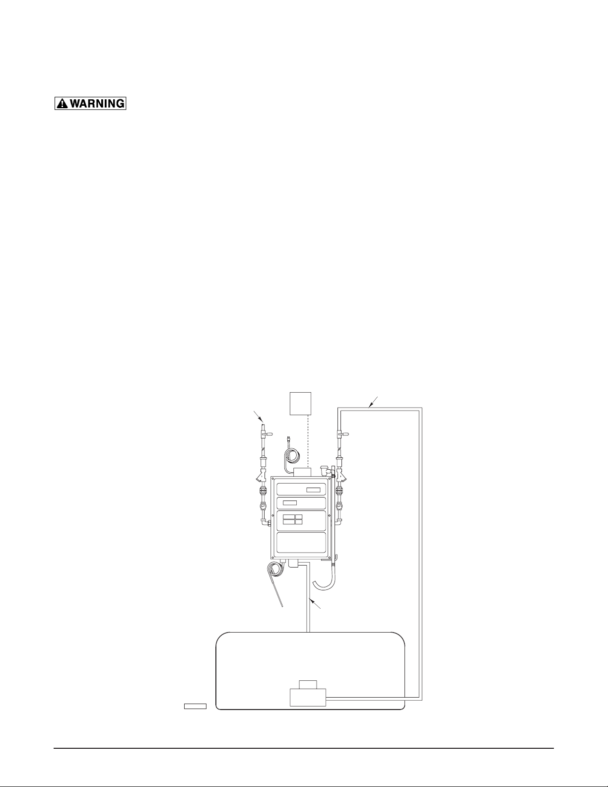
WATER METER WITH OPTIONAL WATER CHILLER AND PLUMBING CONNECTIONS
NOTE: The Hot and Cold Water Supply lines can vary in location.
Fig. 4
PL-57354
Cold Water
Supply Line
Hot Water
Supply Line
120 VAC
J-Box (230/250 VAC)
Test Flow
Discharge Line
Pump
Water Chiller Reservoir or Sink

– 9 –
WATER METER WITH PLUMBING CONNECTIONS
PL-57355
Cold Water
Supply Line
Hot Water
Supply Line
Power Cord
(120 VAC Supply)
Junction
Box
Dispenser
Hose
Dispenser
Hose Hook
Vacuum
Breaker
Hand Held
Temperature Probe
Test Flow
Discharge Line
Union
Connector
90 Elbow
Shutoff Valve
(Not Supplied)
T-Fitting with
Pressure Gauge
(Set to 30 PSIG)
Dual Check
Valve
Y-Strainer
Pressure
Regulator
NOTE: The Hot and Cold Water Supply lines can vary in location.
Fig. 5

– 10 –
ASSEMBLY
The water meter is supplied with external ttings/components that must be assembled before the water
supply is connected.
Qty. FITTING/COMPONENTS Qty. FITTING/COMPONENTS
2 Pressure Regulator 2 Dual Check Valve
2 90 Degree Elbow 1 Vacuum Breaker
1 Dispenser Hose 2 T-Fitting With Pressure Gauge
2 Y-Strainer 1 Hand Held Temperature Probe
1 20" Bypass Line Hose and Fittings
(For water chiller option only. See Fig. 4 under Plumbing Connections.)
• Assemble the ttings to the water meter as shown in Fig. 5. Use teon tape or pipe joint compound
when assembling.
• The union connection on the water meter has a at doughnut gasket. Make sure the gasket is in
place before connecting any ttings.
• Plug the hand held temperature probe into the end of the exible cable attached to the bottom
panel of the meter.
SETTING WATER PRESSURE
For the water meter to operate properly, the water pressure should be set at 30 psi (207 kPa) on each
regulator while it is operating at 125°F (52°C). See Operation on the following pages for a description of
the control panel.
1. Press CHANGE UNITS to select English or Metric units. (If the CHANGE UNITS key is locked, see
Locking and Unlocking the Change Units.)
2. Press SET TEMP and enter 125°F (52°C) on the numeric key pad. The water temperature value is
displayed in the WATER TEMPERATURE window.
3. Hook the dispensing hose over the rim of a sink or drain.
4. Press SET AMOUNT and enter 20 lbs 00 oz.
5. Press START. The water begins dispensing from the bypass line. The actual water temperature of
the owing water is displayed in the WATER TEMPERATURE window.
6. Allow the owing water temperature to reach 125°F (52°C) and switch over to delivery.
7. Adjust both hot and cold water regulators until the pressure gauges read 30 psi (207 kPa).
Ce manuel convient aux modèles suivants
2
Table des matières
Autres manuels baxter Instrument de mesure


Manuels Instrument de mesure populaires d'autres marques


Endress+Hauser
Endress+Hauser Proline Promag 50 Caractéristiques techniques

Siemens
Siemens SITRANS F Coriolis FCT030 Manuel de la liste des pièces

KLINGER
KLINGER CMF V Series Manuel utilisateur

EXFO
EXFO FTB-2 Manuel d'exploitation et d'entretien

Keysight
Keysight M8290A Manuel utilisateur

ADTEK
ADTEK MW-5 Manuel utilisateur