Backflow Direct Magnum 20(x) Caractéristiques techniques

6” – 8” Magnum 20(x) Maintenance Instructions
At Backflow Direct we are committed to making our products as easy to install as possible. We design for
most contingencies, but installation may be different based on your regional regulations or system design.
We are continually improving our products and instructions –please help us by providing recommendations
as to how we can improve or products or instructions.
If you have any difficulties at all, please give us a call. Thank you for purchasing our product!
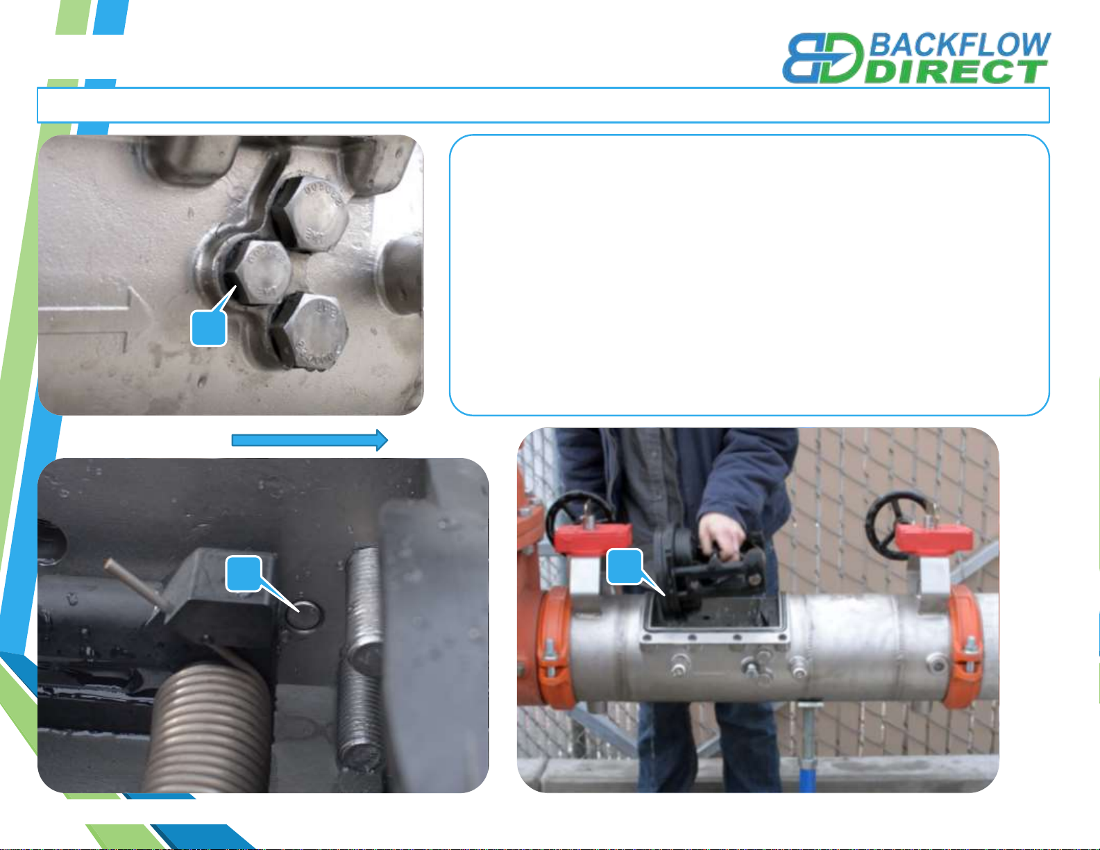
IMPORTANT NOTE: We use Stainless Steel Hardware where possible. Therefore, it is best to have Silver Anti-
seize available to use on all non-wetted bolts—only a small amount is needed.
WARRANTY INFORMATION: Please visit our website for our official warranty www.backflowdirectwarranty.com
READ INSTRUCTIONS IN FULL BEFORE INSTALLATION.
QUESTIONS? CALL 916-760-4524 M-F 8:00 AM –4:30 PM PST
REV: A | 03/02/2018 | BD-INST-020X

6”-8” Magnum 20(x) Maintenance Instructions
BD-INST-020X | Rev A | 03/02/2018 | Copyright 2011 Backflow Direct, LLC Page 2 of 16
#2 Philips Head Screwdriver
#2 Flathead Screwdriver
Adjustable Wrench
Ratchet
Wood Block - 2” x 4” x 5”
Wood Block – 1” x 2” x 16”
Backflow Direct Test Cock Wrench
Expanding Pipe Pliers
15/16” Socket
1 1/8” Socket
Tools Required: This list is the recommended tools for ease of installation. Other versions of the same tool can be used. For
example,Allen Wrenches instead of Allen Drive Sockets.
QUESTIONS: Please call us at 916-760-4524 M-F 8:00 AM –4:30 PM PST or email us at techhelp@backflowdirect.com

6”-8” Magnum 20(x) Maintenance Instructions
BD-INST-020X | Rev A | 03/02/2018 | Copyright 2011 Backflow Direct, LLC
Closing Shut-Off Valves Prior to Maintenance
1. Slowly rotate Shut-Off Valve #2 Handle (B) clockwise
to the closed position. Flag perpendicular to flow (A).
2. Slowly rotate Shut-Off Valve #1 Handle (C) clockwise
to the closed position. Flag perpendicular to flow (A).
Note: When yellow/orange position indicator flags are
parallel with the flow of water the shut-off valves are in the
open position. Before doing any maintenance be sure the
yellow or orange flow indicators (flags) are perpendicular
to the flow of water valve body indicating shut-off valves
are in the closed position (A).
Note
B
FLOW C
A
Page 3 of 16
FLOW
A

6”-8” Magnum 20(x) Maintenance Instructions
BD-INST-020X | Rev A | 03/02/2018 | Copyright 2011 Backflow Direct, LLC
Opening Test Cocks and BleedingAll Pressure from the Line Before Maintenance
1. DO NOT OPEN Main Test Cock Number 1,
as it is still subject to line pressure.
2. Using the Backflow Direct test cock wrench or
a small adjustable wrench open (A) Main Test
Cock Number 4. (Test Cock is open when
wrench flats are parallel to water flow through
test cock)
3. Using the Backflow Direct test cock wrench
or a small adjustable wrench open Main
Test Cock Number 3.
4. Using the Backflow Direct test cock wrench
or a small adjustable wrench open Main
Test Cock Number 2.
BD-INST-020X | Rev A | 03/02/2018 | Copyright 2011 Backflow Direct, LLC
A
A
Page 4 of 16
FLOW

6”-8” Magnum 20(x) Maintenance Instructions
BD-INST-020X | Rev A | 03/02/2018 | Copyright 2011 Backflow Direct, LLC
Removing Access Port Cover Plate
1. Using a 15/16”socket wrench loosen all eight bolts on the access port
cover plate (A).
2. Remove bolts and tapered washers (B) and store in a safe place. Be
careful not to lose tapered washers as the access cover will not seal
properly without the tapered washers.
3. Remove access port cover plate (C). Do not remove Access Port O-ring
(D).
BC
A
BD-INST-020X | Rev A | 03/02/2018 | Copyright 2011 Backflow Direct, LLC Page 5 of 16
D
6”-8” Magnum 20(x) Maintenance Instructions
BD-INST-020X | Rev A | 03/02/2018 | Copyright 2011 Backflow Direct, LLC
Removing the First Dual-Action Check Module
1. Use a 15/16”Socket Wrench to loosen the check retainer bolts on both
sides of the valve body (A). Do not completely remove check retainer
bolts from valve body. Merely loosen the bolts until the ends of the bolts
are flush with the inner wall of the valve body(B). Allow easy removal of
Check Modules
2. Insert a flathead screwdriver between the inner valve body and the First
Check Module Flange (C), gently coax the First Check Module in the
downstream direction until the First Check Module can easily be
removed from the access port by hand.
A
B
BD-INST-020X | Rev A | 03/02/2018 | Copyright 2011 Backflow Direct, LLC Page 6 of 16
C
FLOW

6”-8” Magnum 20(x) Maintenance Instructions
BD-INST-020X | Rev A | 03/02/2018 | Copyright 2011 Backflow Direct, LLC
Removing the Second Dual-Action Check Module
1. Use a 1 1/8”Socket Wrench to loosen the Check Retainer Bolts on
each side of the valve body (A). Do not completely remove check
retainer bolts from valve body. Merely loosen the bolts until the ends
of the bolts are flush with the inner wall of the valve body(B).
2. Insert a flathead screwdriver between the inner valve body and the
Second Check Module Flange (C), gently coax the Second Check
Module in the upstream direction until the Second Check Module can
easily be removed from the access port by hand.
A
A
C
BD-INST-020X | Rev A | 03/02/2018 | Copyright 2011 Backflow Direct, LLC Page 7 of 16
B
FLOW

6”-8” Magnum 20(x) Maintenance Instructions
BD-INST-020X | Rev A | 03/02/2018 | Copyright 2011 Backflow Direct, LLC
Maintenance of First Dual-Action Check Module
1. Use a #2 Philips Head Screwdriver to remove Tower
Screws (A) from the First Check Seat (B) The Double
Torsion Spring is captured (C) and does not to be
retained during maintenance.
2. After removing the Tower Screws (A) Examine the
Elastomer Disk (D) and Check Seat (E) for fouling or
damage.
3. Should Elastomer Disk (D) need replacement unscrew
Disk Retainer Screws (F) and remove Disk Retainer (G).
Carefully remove and replace Elastomer Disk (D).
When replacing Elastomer Disk (D) be certain that no
air, water or debris is trapped in the Clapper (H) cavity
behind the Elastomer Disk (D).
A
BD-INST-020X | Rev A | 03/02/2018 | Copyright 2011 Backflow Direct, LLC
4. Reverse the order of the above instructions to reassemble check.
•Elastomer Disk must be flat in Clapper (H) cavity before
tightening Disk Retainer Screws (F).
•Do not cross thread Disk Retaining Screws (F).
B
E
D
F
DG
Page 8 of 16
H
C

6”-8” Magnum 20(x) Maintenance Instructions
BD-INST-020X | Rev A | 03/02/2018 | Copyright 2011 Backflow Direct, LLC
Maintenance of First Dual-Action Check Module
BD-INST-020X | Rev A | 03/02/2018 | Copyright 2011 Backflow Direct, LLC Page 9 of 16
Note: The diagram below shows the correct orientation of the First Dual-Action Check Module when being re-attached to the seat. In
order to maintain the performance of the valve pay attention to the proper orientation of the check module.

6”-8” Magnum 20(x) Maintenance Instructions
BD-INST-020X | Rev A | 03/02/2018 | Copyright 2011 Backflow Direct, LLC
Maintenance of Second Dual-Action Check Module
H
BD-INST-020X | Rev A | 03/02/2018 | Copyright 2011 Backflow Direct, LLC
AC
B
E
D
F
D
G
Page 10 of 16
1. Use a #2 Philips Head Screwdriver to remove Tower
Screws (A) from the Second Check Seat (B) The Double
Torsion Spring is captured (C) and does not to be
retained during maintenance.
2. After removing the Tower Screws (A) Examine the
Elastomer Disk (D) and Check Seat (E) for fouling or
damage.
3. Should Elastomer Disk (D) need replacement unscrew
Disk Retainer Screws (F) and remove Disk Retainer (G).
Carefully remove and replace Elastomer Disk (D).
When replacing Elastomer Disk (D) be certain that no
air, water or debris is trapped in the Clapper (H) cavity
behind the Elastomer Disk (D).
4. Reverse the order of the above instructions to reassemble check.
•Elastomer Disk must be flat in Clapper (H) cavity before
tightening Disk Retainer Screws (F).
•Do not cross thread Disk Retaining Screws (F).
Autres manuels Backflow Direct Unité de contrôle


Manuels Unité de contrôle populaires d'autres marques

Festo
Festo Compact Performance CP-FB6-E Manuel de la liste des pièces

Elo TouchSystems
Elo TouchSystems DMS-SA19P-EXTME Manuel utilisateur

JS Automation
JS Automation MPC3034A Manuel utilisateur

JAUDT
JAUDT SW GII 6406 Series Guide rapide

Spektrum
Spektrum Air Module System Manuel utilisateur

BOC Edwards
BOC Edwards Q Series Manuel utilisateur


