
Autel ATS100 Manuel utilisateur
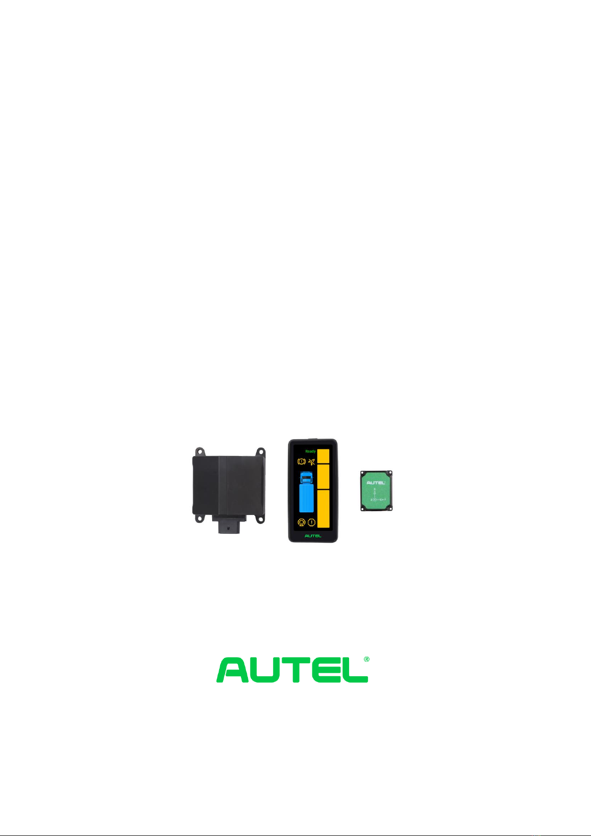
I
ATS100 (With GPS)
Intelligent Turn Assist
System User Manual
Autel Intelligent Automobile Co., Ltd.

II
Trademarks
Autel®, MaxiSysTM, MaxiDAS®, MaxiScan®, MaxiTPMS®, MaxiVideoTM, MaxiRecorderTM, and
MaxiCheck TM are trademarks of Autel Intelligent Technology Corp., Ltd., registered in China, the
United States, and other countries. All other marks are trademarks or registered trademarks of their
respective holders.
Copyright Information
No part of this manual may be reproduced, stored in a retrieval system, or transmitted in any form
or by any means, electronic, mechanical, photocopying, recording, or otherwise without the prior
written permission of Autel Intelligent Technology Corp., Ltd.
Disclaimer of Warranties and Limitation of Liabilities
All information, specifications and illustrations in this manual are based on the latest information
available at the time of printing.
Autel Intelligent Technology Corp., Ltd. reserves the right to make changes at any time without
notice. While information in this manual has been carefully checked for accuracy, no guarantee is
given for the completeness and correctness of the contents, including but not limited to product
specifications, functions, and illustrations.
Autel Intelligent Technology Corp., Ltd. will not be liable for any direct, special, incidental, or
indirect damages, or for any economic consequential damages (including lost profits) as a result of
using the product.
IMPORTANT
Before operating or maintaining this unit, please read this manual carefully, paying extra attention
to the safety warnings and precautions.
For Services and Support
Web: www.auteltech.cn
Email: Support@auteltech.net
Hotline: 0086-755-2267-2493 (China HQ) / 1-855-AUTEL-US (288-3587) (NorthAmerica) /
0049 (0) 6103-2000520 (Europe) /+045 5948465 (APAC) / +971 585 002709 (IMEA)
For technical assistance in all other markets, please contact your local distributor.

III
Table of Contents
1. ATS100 Turn Assist System Introduction......................................................................... 1
1.1 ASR100 Radar Introduction............................................................................................... 2
1.2 Warning Display................................................................................................................ 3
1.3 GPS&IMU Module............................................................................................................ 6
1.4 System Connections & Wire Harness Description ............................................................ 7
2. User Guide....................................................................................................................... 10
2.1 Radar Installation ........................................................................................................... 10
2.2 Radar Wiring.................................................................................................................. 13
2.3 Input Signal Access........................................................................................................ 14
2.4 Power Access ................................................................................................................. 15
2.5 GPS&IMU Module Installation ..................................................................................... 15
2.6 Diaplay Screen Installation............................................................................................. 16

1
1. ATS100 Turn Assist System Introduction
ATS100 is a turn assist system with accurate target detection and warnings for vehicle
blind spots. The system components are as followes: a millimeter-wave radar with
operation frequency 76-77GHz and max RF output power 12dbm, a spirit level, a
mounting bracket (optional), a warning screen, a GPS&IMU module and the cable. The
millimeter-wave radar can accurately measure the target distance, speed, angle, and
other information through the difference in echoes between the transmitting and
receiving electromagnetic waves. It is an all-weather and all-day operational turn assist
system with working temperature from -40℃-85℃. The warning screen warns the
driver of a dangerous target in the blind spot and reminds the driver to make timely
adjustments to the driving trajectory, to avoid accidents.
The ATS100 turn assist system covers 180°on one side, ensuring no blind spots, with
target detection range up to 80 x 4.5 m. With a compact structure, it comes with collision
pre-determination and graded alarm function, can integrate with external CAN
(Controller Area Network) and CAN FD (Flexible Data) interfaces, and supports 12 V
or 24 V supply voltage.
Figure 1-1ASR100 radar coverage
Warning targets of ATS100 turn assist system include:
Dynamic vulnerable road users, moving at speeds greater than 3 km/h, including
pedestrians, bicycles, electric bicycles, etc.
Dynamic cars, moving at speeds greater than 10 km/h.
Note: The safe use distance of the system needs to be greater than 4cm.

2
1.1 ASR100 Radar Introduction
The ASR100 77 GHz Millimeter-Wave Radar is a compact, rugged radar sensor
designed and manufactured by Autel Intelligence Vehicle® in China for side blind zone
warnings for heavy trucks/buses, etc. The ASR100 meets automotive grade standard
for professional commercial vehicles and has an IP69K rating, in line with the
commercial vehicle use environment.
Figure 1-2ASR100 dimensions
Performance Parameter:
Working Frequency
76-77GHz
Maximum Detection Range
±80m(Vehicle)
±40m(pedestrian/bicycle)
Working Mode
Low Speed
High Speed
Minimum Detection Range
0.25m
0.9m
Distance Resolution
0.31m
0.96m
Distance Accuracy
±0.16m
±0.5m
Velocity Range
±60km/h
±150km/h

3
Velocity Accuracy
±0.43km/h
Velocity Resolution
0.86km/h
Horizontal Angle
180°
Angle Accuracy
±0.8°
General Parameter:
Size
115mmX95mmX41mm
Weight
230g
Power Consumption
6.5W
Communication Interface
CAN2.0 , CAN_FD
Working Voltage
8V - 32V;
Passenger Vehicle 12V,
Commercial Vehicle 24V
Working Temperature
-40°C ~ 85°C
Storage Temperature
-40°C ~ 105°C
Installation angle redundancy
-5°~5°
Protection Rating
IP69K
Operation Cycle
60ms
1.2 Warning Display
The ATS100 turn assist system employs a precision sensing system to predict future
collision probability with the target and provides users with dynamic sensing and
display-based intelligent warnings, to remind drivers to take preventative measures in
time to reduce the possibility of accidents. The warning display screen supports
adaptive brightness control, enabling the screen’s brightness to adjust based on the
brightness of the surrounding environment, thereby reducing eye-fatigue for drivers
during the night.

4
Figure 1-3 Display size
The warning function is divided into three levels as follows: (Note: Prerequisites for
enabling the warning function: the speed of the vehicle is <30km/h)
Level 1 warning: The steering wheel angle is less than 30°, , and the target enters
the warning range, then a section of warning light LEDs, displayed in Figure 1-4,
light up.
Level 2 warning: The vehicle is turning to the right, the steering wheel angle is
greater than 30°or turn on the turn signal (when the turn signal is connected), and
it is expected that the vehicle and the target will collide within a certain amount of
time, then a section of warning light LEDs start flashing.
Level 3 warning: The vehicle is turning to the right, the steering wheel angle is
greater than 30°or turn on the turn signal (when the turn signal is connected), and
the vehicle and the target collision is imminent within a short amount of time, then
the warning light will start flashing and a warning sound is generated.
The driver can get the approximate location of the target based on the section of warning
light LEDs that are on or are flashing.
The detailed description of each warning light on the display is as follows:

5
Figure 1-4 Description of warning light
①Warning module power and status indicator: lights up when the status of the warning
module is normal.
②Brake indicator: This light flashes when actively braking. (Currently this function is
not available).
③GPS fault indicator: on when GPS sensor has no signal (temporary), flashing when
GPS sensor has faulty signal.
④Warning light: provides early warning of dangerous targets. The warning area is
divided into three different priorities: Zone top (2-5 m in front of the front of the
vehicle), Zone central (2 m in front of the front of the vehicle- 7 m behind the front of
the vehicle), and Zone bottom (7-30 m behind the front of the vehicle), If there are
multiple targets in Zone top, central or bottom at the same time, give priority to Zone
central, then Zone bottom, and then Zone top.
⑤Vehicle model: for reference; is in a steady on state after power on.
⑥Radar status indicator: steady on state indicates a temporary radar failure, usually
caused by factors such as radar being blocked, bad weather conditions; flashing
indicates a permanent radar failure, requiring professional repair.
⑦System fault indicator: The indicator light is on when there is a fault in the entire
system.

6
Troubleshooting
Table 1-1 Fault Description and Troubleshooting
Status Icon
Fault
Description
Repair Instructions
Warning
module power
and status
indicator
does not light
up after power
on
Hardware failure and needs to be replaced
Radar status
indicator
The fault light
is always on
possible reason:
1. Obstructed by objects, such as snow, mud, etc.
2. Extreme weather, heavy rain and snow, etc.
3. The installation angle is greater than 5°
Radar status
indicator
Fault light
flashes
Hardware failure and needs to be replaced
System fault
indicator
Fault light
flashes
Hardware failure and needs to be replaced
GPS fault
indicator
Fault light
flashes
Restart after power off, if the fault still exists, you
need to replace the hardware
1.3 GPS&IMU Module
This module integrates high-precision gyroscope, accelerometer, GPS module, adopts
high-performance microprocessor and advanced dynamic solution and Kalman
dynamic filter algorithm, which can quickly solve the current real-time motion attitude
of the module. Using advanced digital filtering technology can effectively reduce
measurement noise and improve measurement accuracy. The module integrates an
attitude solver and cooperates with the dynamic Kalman filter algorithm to accurately
output the current attitude of the module in a dynamic environment. The attitude
measurement accuracy is 0.05 degrees static and 0.1 degrees dynamic, with extremely
high stability and performance even better than some professional inclinometer.

7
1.4 System Connections & Wire Harness Description
Connect each port of the radar, display, GPS&IMU module wiring harness as shown
below.
Figure 1-5 System connections diagram
Radar Harness Description
In the figure below, the P1 connector is connected to the radar; it has 8 pins and the pin
order is shown as below. The pin number in the figure corresponds to the pin definition
in Table 1-2. The P2 connector is connected to the GPS&IMU module; it has 8 pins,
and the pin number of P2 in the figure corresponds to the pin definition in Table 1-3.
The P3 connector is connected to the vehicle and power supply, it has 6 pins, and the
pin number of P3 in the figure corresponds to the pin definition in Table 1-4. The end
of each cable has a printed label. Please check it carefully during installation. Do not
turn the power on if the connectors are improperly connected.
Figure 1-6 Radar wiring harness diagram
Radar interface P1 definition table:
Table 1-2 Definition of Radar Interface P1
No.
Definition
Range
Cable color
Autres manuels pour ATS100
1
Table des matières
Manuels Unité de contrôle populaires d'autres marques

Festo
Festo Compact Performance CP-FB6-E Manuel de la liste des pièces

Elo TouchSystems
Elo TouchSystems DMS-SA19P-EXTME Manuel utilisateur

JS Automation
JS Automation MPC3034A Manuel utilisateur

JAUDT
JAUDT SW GII 6406 Series Guide rapide

Spektrum
Spektrum Air Module System Manuel utilisateur

BOC Edwards
BOC Edwards Q Series Manuel utilisateur


