Aunex AC Series Manuel utilisateur

AC Series 1 Channel Ampliers
Compact Class D Mono Amplier Series
Models: AC500.1D, AC1000.1D, AC1500.1D
Installation and Operation Manual
Please take time to thoroughly read through this manual to familiarize yourself with your new amplier.
This will ensure that your amplier will perform at its optimum capabilities.
Para obtener una copia de este manual en español, visite www.aunexusa.com y luego vaya a la página
del producto que necesita. Haga clic en la pestaña Soporte y descargue su manual en español.
AC500.1D
CLASS D MONOBLOCK

1
Congratulations and thank you for purchasing an Aunex AC Series
Amplier. This product has been engineered and manufactured
utilizing precision quality parts and craftsmanship. Improvements
in sound quality and system performance will be greatly enhanced
with the use of this amplier.
To ensure maximum performance we highly recommend you have
your new Aunex product installed by an Authorized Aunex Dealer.
Should you decide to install this product yourself, please make
sure to read this manual thoroughly to familiarize yourself with
the necessary installation requirements and tuning procedures.
Please read your warranty and retain a copy of your purchase
receipt and original carton should your Amplier ever needs to be
serviced and warranted.
Visit our website for the latest information on all Aunex products
at: www.aunexusa.com. If you have any questions regarding
this product, please contact your Authorized Aunex Dealer for
assistance or call / email Aunex Technical Support Department at
(909) 589-5010 / [email protected].
Caution: Continuous exposure to sound pressure levels over 100dB
may cause permanent hearing loss. High powered audio systems can
produce sound pressure levels that can exceed over 150dB. Please limit
your exposure to continuous high listening volumes.

2
Feature Set of the AC Series Mono Ampliers
• Heavy Density Aluminum Extruded Heatsink
• 4 Layer PCB, SMD Technology
• Conformal Coated PCB
• Dierential Balanced RCA Inputs
• Output Clipping Indicators
• Fully Variable Crossover 24dB/Octave
• Boost Eq. 0 – 18dB @ 45Hz Center
• Fully Variable Infrasonic Filter 10Hz – 50Hz @ 24dB/Octave
• Autosensing in High Level Input Mode
o Remote Input Becomes Remote Output Trigger if High
level Input is used.
• Power and Protection Logo Illuminated Status Indicator
o Blue Indicates Amplier is powered On.
o Red Indicates the Amplier is in Protection
• Blue Illuminated Power Input and Speaker Output Terminals
• 4 Gauge Power & Ground Terminals
• 8 Gauge Speaker Output Terminals
• Advance Protection Circuit Monitoring: Short, Thermal,
Overload and Impedance
• Remote Level Controller
• Finish: Anodized with Texture Paint
What’s Included
• (1) AC Series Mono Class D Amplier
• (1) Remote Level Controller, Cable and Wing Adapter
• (1) In-Line Fuse Holder with Mini ANL Fuse
o AC500.1D is supplied with 2 x 30A Fuses
o AC1000.1D is supplied with 3 x 30A Fuses
o AC1500.1D is supplied with a 200A Fuse
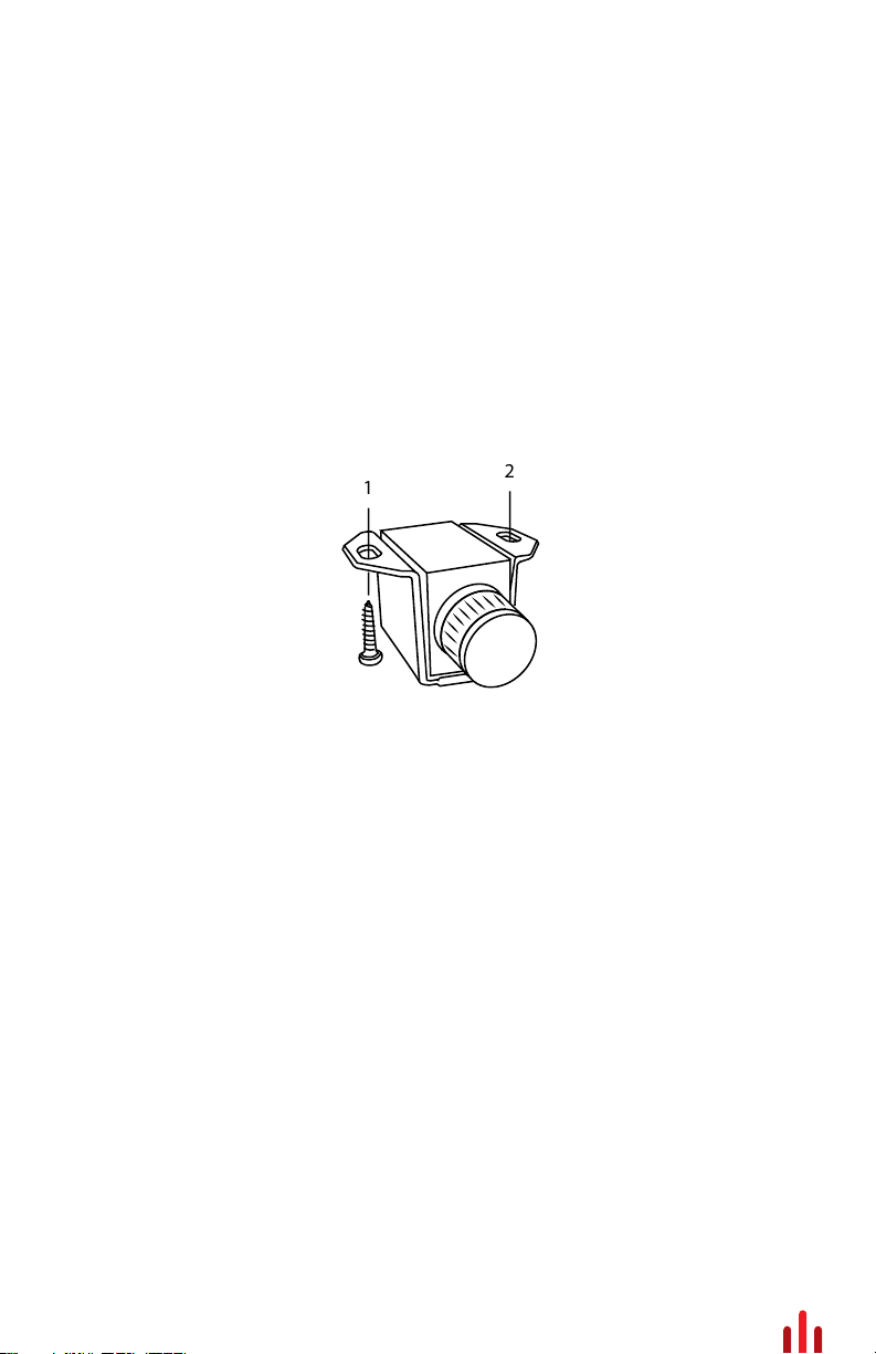
• (6) Self Tapping Screws; (4) for Amplier, (2) for Remote
• (2) Allen Wrenches
• (1) Instruction Manual
• (1) Sticker

3
Important Safety Considerations
• To prevent personal injury and damage to the unit, please read
the following instructions in this manual.
• This product is designed to use in vehicles with 12Volt,
negative-ground electrical systems.
• Install this product in a dry location away from your vehicles’
safety equipment (airbags, seat belt system, etc.). Water and
humidity may damage internal components.
• Use the included mounting accessories to secure this product
so that it does not come loose.
• Check before drilling to make sure you do not drill into any vital
vehicle system.
• Protect all system wiring from sharp metal edges.
• Do not disassemble or modify this unit; doing so will void your
manufacturer’s warranty.
Important Installation Precautions
Installation of mobile audio equipment requires experience.
Although this manual provides general installation procedures,
it will not show the exact installation method for your particular
vehicle.
If you do not have the required knowledge and experience,
we recommend that you have your equipment installed by an
Authorized Aunex Dealer.
• Turn o all stereo and other electrical devices before you begin.
• Disconnect the negative (-) lead from your vehicle’s battery to
avoid an electrical short. Reconnect the negative lead to your
battery once your installation is complete. So, in other words
the negative lead from our vehicle’s battery is the rst
connection you remove before starting your installation and
the last connect your make after you nish your installation.
• Check your mounting location to make sure there is sucient
room for your installation placement preference.

4
Mounting Placement
Choose a structurally sound location to mount your Aunex
amplier, making sure there are no items behind the area where
the screws will be driven.
For optimum sound quality, it is highly recommended that you
purchase Aunex wiring accessories as they are designed to give
your ampliers high-quality signal it needs to operate at peak
performance levels. Aunex provides a wide selection from
RCA cables and power wire to speaker wire and battery
connectors.
Important Installation Precautions Continued
• Install this product in a dry location away from your vehicles’
safety equipment. Each AC Series amplier circuit board has
been coated with a protective layer of Conformal Coating. This
will help protect the electronic circuit from harsh environments
that may contain humidity and a range of airborne contaminants
and varying temperatures. However prolonged exposure to
water and high humidity may damage internal components in
time. Keeping the amplier dry and installed in a well-ventilated
area will help ensure many years of listening enjoyment.
• When running power cables through sheet metal it is best to
use grommets and loom to properly insulate your cables from
metal edges.
• Avoid mounting the amplier with the top ns facing down as
this may increase the operating temperature of your amplier.
• If mounting underneath a seat, make sure that there is at least
1 inch (25mm) of space above the amplier to permit proper
cooling.
• Avoid mounting the ampliers on a subwoofer enclosure as
prolonged excessive vibration may damage your amplier.

5
Side Panel Layout
1
9
2
10 11 12 13
3 4 5 6 7 8
6
1. Remote Level Control: With the Remote Level Control plugged
to your amplier, you can now adjust the amount of output from
the convenience of this controller. There are several mounting
options for your controller. With the supplied wing attachment,
you can mount the controller under your dash. Should you want
to mount the controller ush to your dash, arm rest or any other
panel of your vehicle the wing attachment will more than likely
not be needed.
2. Clipping Led Indicators: These LED’s will light up when the
amplier output signal is being clipped. When the LED’s starts
to glow, your amplier output is between 1-2% THD (Total
Harmonic Distortion). When the clipping indicators are fully lit,
your amplier output is between 6-7% THD (Total Harmonic
Distortion). The ideal gain setting is where the clip indicators
are not lit allowing the amplier to send undistorted clean
output. Setting the ampliers gains improperly where the clip
indicators are always lit will over-work the amplier and may
cause excessive heat building and possibly product failure.
3. Boost Eq: Your AC Series ampliers incorporates a Boost Eq.
circuit that can increase output 0-18dB centered at 45Hz. Note if
you turn up the Boost Eq, you will need to readjust the Input
Gains to avoid clipping the output signal. Using the Clipping
LED’s will help set your Boost Eq and Input Gains properly.
12
Side Panel Layout Continued

7
4. Infrasonic Filter: This variable potentiometer will provide a roll
o point for lower frequencies (10Hz – 50Hz variable) that could
potentially damage your subwoofers from over-excursion. The
frequency setting for your Infrasonic Filter is to be set relative
to your subwoofers low-frequency capabilities along with
enclosure tuning. In a sealed box Aunex recommends setting
the Infrasonic Filter between 25Hz – 35Hz. In a ported enclosure
Aunex recommends setting the Infrasonic lter at ½ an Octave
below your tuned frequency.
For example, let say your ported enclosure is tuned at 40Hz.
Take ½ of 40Hz which is 20Hz (this is one octave lower). Now
take another half o 20Hz which is then 10Hz (this is half an
octave lower). Now take 10Hz from 40Hz which is 30Hz and
where you should set your Infrasonic Filter.
5. Low Pass (LP) Filter Frequency Filter: This potentiometer
allow you to adjust the crossover frequency from 50Hz – 250Hz.
6. Phase Switch: Depending on the absolute phase of your main
speakers and amplier and the distances of the subwoofers
and the main speakers from the main listening position, the
bass in the crossover region maybe smoother if you reverse the
subwoofer’s phase. Try both settings to determine which
polarity produces the best overall bass performance in your
system. Typically though, phase is left at the 0⁰ for most
installation.
7. Input Gain: Use this Input Gain Potentiometer to match the
output voltage of your headunit / source unit to the input circuit
of your amplier. This Input Gain is not a volume knob. A
simple method of setting your Input Gain is to turn your headunit
/ source unit up to approximately ¾ volume. Then slowly adjust
your Input Gain on your ampliers clockwise until you can hear
distortion from your subwoofer(s). Then turn the gains down
(counterclockwise) till the distortion is no longer heard and your
clipping indicators are not lit.
Side Panel Layout Continued

8
8. Low Level RCA Inputs: These are your dierential
balanced inputs that are used to connect audio signal from
your headunit / source unit to your amplier. Your AC Series
Amplier is capable to receiving either High Level
Speaker Outputs or Low-Level RCA cables. If you are
using High Level Speaker outputs, you may need a high
to low level adapter such as the Aunex AP-SL2 adapter.
9. Speaker Outputs: Your AC amplier speaker outputs are
designed to accept 16 AWG to 8 AWG wire. Turn the set
screws on this terminal counterclockwise to loosen the
screws using the supplied Hex wrench. Strip the PVC jacket
from your speaker wire ½ inch (12mm). Then insert the bare
wire into the terminal block so that no bare speaker wire is
exposed. Then tighten the set screw by turning it clockwise.
Loading your amplier below the recommended
impedance rating found on page 13 is not
recommended and may cause your amplier to
enter into protection mode and may void your warranty.
For maximum current ow, Aunex recommends that you tin
your speaker wire before connecting it to the speaker output
terminals. In addition, Aunex recommends using high
quality 100% OFC (Oxygen Free Cooper) or Tinned 100% OFC
speaker wire. This will ensure that your speaker /
subwoofer receives maximum output from your amplier.
10. Fuse Holder: This is your fuse block. The AC500.1D
and the AC1000.1D has fuses mounted on the side
panel. The AC1500.1D includes an external fuse holder.
Should there be a short in your system or if your amplier is
being overdriven, these fuse(s) will typically burn to prevent
damage to your amplier. If it is required to replace your
fuse(s), use the same fuse rating that comes with your
amplier. Using a higher fuse may damage your amplier
and will void your warranty.
Side Panel Layout Continued

9
11. +12Volt Positive Terminal: The +12Volt positive terminal is
designed to accept up to 4 AWG wire. Use the supplied fuse
block and make your +12Volt connection directly to the positive
battery post. The Fuse should be installed within 18” (457mm)
of the battery. This fuse is vital to protecting the vehicle and
amplier from a dead short. Turn the set screws on this terminal
counterclockwise to loosen the screw using the supplied Hex
wrench. Strip the PVC jacket from your speaker wire ½ inch
(12mm). Then insert the bare wire into the terminal block so that
no bare power wire is exposed. Then tighten the set screw by
turning it clockwise.
For maximum current ow, Aunex recommends that you tin
your power wire before connecting it to the +12Volt terminal. In
addition, Aunex recommends using high quality 100% OFC
(Oxygen Free Cooper) or Tinned 100% OFC speaker wire. This
will ensure that your speaker / subwoofer receives maximum
output from your amplier.
12. Remote Input Terminal: This terminal must be connected to
a switched +12Volt source. If the source unit does not have a
remote Turn on lead, then a switched +12 supply should be
used such as the ACC +12Volt. Run an 18-gauge wire from the
Remote Turn-On Lead from your headunit / source unit to this
terminal.
If you are using the High-Level Speaker Outputs connection
to the ampliers’ RCA inputs, you do not need to connect
a remote input to your amplier. Your amplier will
automatically detect the speaker signal and will turn on
your amplier via its DC Oset circuit. In addition, the
remote input terminal then becomes a remote output
trigger which can be used to turn on another amplier
or processor that requires a +12volt remote connection.
Side Panel Layout Continued
Autres manuels pour AC Series
1
Ce manuel convient aux modèles suivants
3
Table des matières
Autres manuels Aunex Amplificateur


