ATH-Heinl ATH W22 Manuel utilisateur
OPERATING INSTRUCTIONS
ATH W22

® Copyright ATH-Heinl GmbH & Co. KG, 2019, All rights reserved / Misprints and technical changes reserved / As of: 2019-03
Manufacturer ATH-Heinl GmbH & CO.KG
- 2 -
Contents
1.0 INTRODUCTION ................................................................................................................... - 3 -
1.1 General Information ........................................................................................................... - 3 -
1.2 Description ........................................................................................................................ - 4 -
1.3 Operation.......................................................................................................................... - 7 -
1.4 Technical Data ................................................................................................................ - 15 -
1.5 Scale Drawing ................................................................................................................. - 16 -
2.0 INSTALLATION ................................................................................................................... - 17 -
2.1 Transport & Storage Conditions ........................................................................................ - 17 -
2.2 Unpacking the machine .................................................................................................... - 18 -
2.3 Delivery Contents ............................................................................................................ - 19 -
2.4 Location .......................................................................................................................... - 21 -
2.5 Fixing ............................................................................................................................. - 22 -
2.6 Electrical Connection ........................................................................................................ - 23 -
2.7 Pneumatic Connection ...................................................................................................... - 23 -
2.8 Hydraulic Connection ....................................................................................................... - 23 -
2.9 Assembly ........................................................................................................................ - 24 -
2.10 Completion of Work ...................................................................................................... - 29 -
3.0 OPERATION ....................................................................................................................... - 30 -
3.1 Operating Instructions ..................................................................................................... - 30 -
3.2 Basic Information ............................................................................................................ - 31 -
4.0 MAINTENANCE ................................................................................................................... - 32 -
4.1 Consumables for installation, maintenance and servicing..................................................... - 32 -
4.2 Safety Regulations for Oil ................................................................................................. - 33 -
4.3 Notes ............................................................................................................................. - 34 -
4.4 Maintenance or Service Plan ............................................................................................. - 34 -
4.5 Troubleshooting / Error Display and Solutions .................................................................... - 35 -
4.6 Maintenance and Service Instructions ................................................................................ - 37 -
4.7 Disposal .......................................................................................................................... - 38 -
5.0 EG-/EU-KONFORMITÄTSERKLÄRUNG / EC-/EU-DECLARATION OF CONFORMITY...................... - 39 -
6.0 APPENDIX .......................................................................................................................... - 40 -
6.1 Pneumatic circuit diagram ................................................................................................ - 40 -
6.2 Electric circuit diagram ..................................................................................................... - 40 -
6.3 Hydraulic circuit diagram .................................................................................................. - 40 -
7.0 WARRANTY CARD ............................................................................................................... - 41 -
7.1 Scope of the Product Warranty ......................................................................................... - 42 -
8.0 INSPECTION LOG ............................................................................................................... - 43 -
8.1 Installation and Handover Log .......................................................................................... - 44 -
8.2 Inspection Plan ................................................................................................................ - 45 -
8.3 Visual inspection (authorised expert) ................................................................................. - 46 -
9.0 SPARE PART BOOK ............................................................................................................. - 50 -
10.0 NOTES ............................................................................................................................... - 73 -
® Copyright ATH-Heinl GmbH & Co. KG, 2019, All rights reserved / Misprints and technical changes reserved / As of: 2019-03
Manufacturer ATH-Heinl GmbH & CO.KG
- 3 -
1.0 INTRODUCTION
1.1 General Information
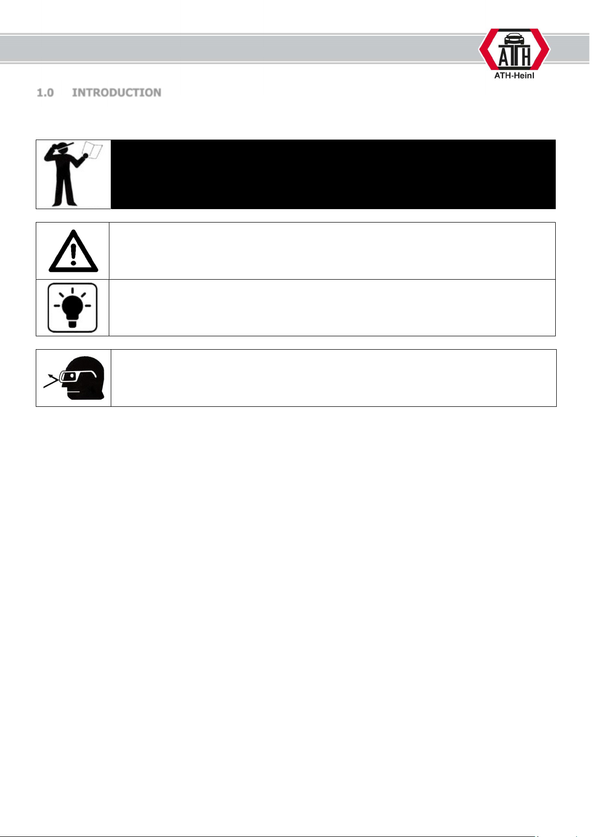
THESE INSTRUCTIONS ARE AN INTEGRAL PART OF THE MACHINE.
THEY MUST BE READ AND UNDERSTOOD BY THE USER.
NO LIABILITY IS ASSUMED FOR ANY DAMAGES CAUSED BY FAILURE TO
FOLLOW THESE INSTRUCTIONS OR THE VALID SECURITY PROVISIONS.
WARNING: Follow the instructions to prevent injury or damage.
TIP: Provides more information on functionality and tips for using the device efficiently.
Appropriate protective clothing must be worn for all work on the described system.
® Copyright ATH-Heinl GmbH & Co. KG, 2019, All rights reserved / Misprints and technical changes reserved / As of: 2019-03
Manufacturer ATH-Heinl GmbH & CO.KG
- 4 -
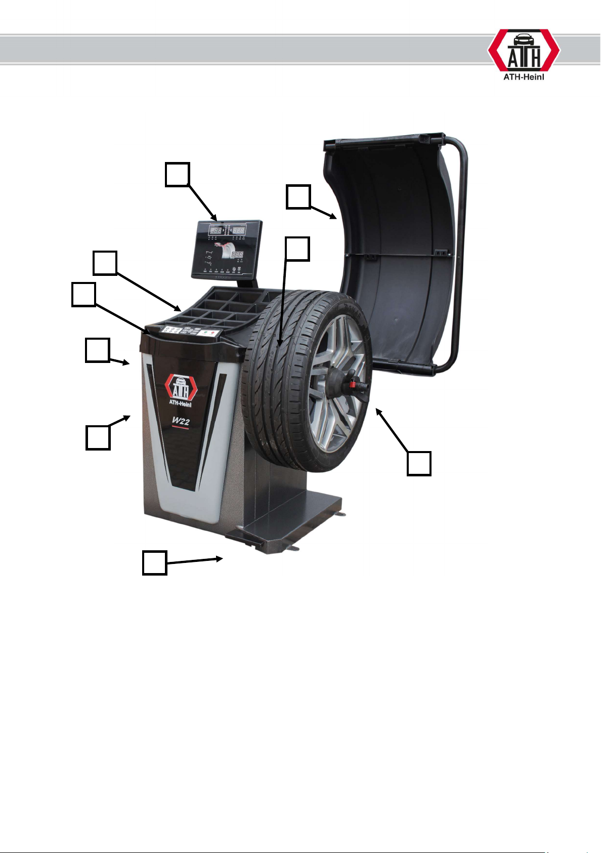
1.2 Description
1. Main switch with emergency stop function
used to switch the balancing machine on and off
2. Cone intake
3. Weight storage
4. Wheel protector
5. Plunge
6. Balancing shaft
7. Display
8. Control
9. Brake pedal
7
2
1
8
3
5
9
6
4
® Copyright ATH-Heinl GmbH & Co. KG, 2019, All rights reserved / Misprints and technical changes reserved / As of: 2019-03
Manufacturer ATH-Heinl GmbH & CO.KG
- 5 -
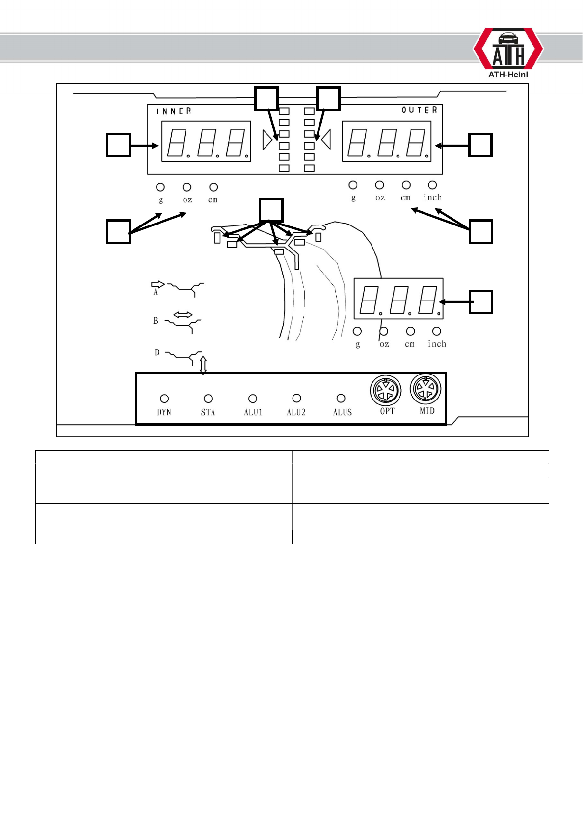
1) Display INTERNAL imbalance 2) Display EXTERNAL imbalance
3) Display position of the INTERNAL imbalance 4) Display position of the EXTERNAL imbalance
5) Display mode 6) Indicator light for measurement unit – mm or
inches
7) Display STATIC imbalance 8) Indicator light for measurement unit – g or
ounces
9) Display weight position
1
3 4
2
5
6
7
8
9
® Copyright ATH-Heinl GmbH & Co. KG, 2019, All rights reserved / Misprints and technical changes reserved / As of: 2019-03
Manufacturer ATH-Heinl GmbH & CO.KG
- 6 -
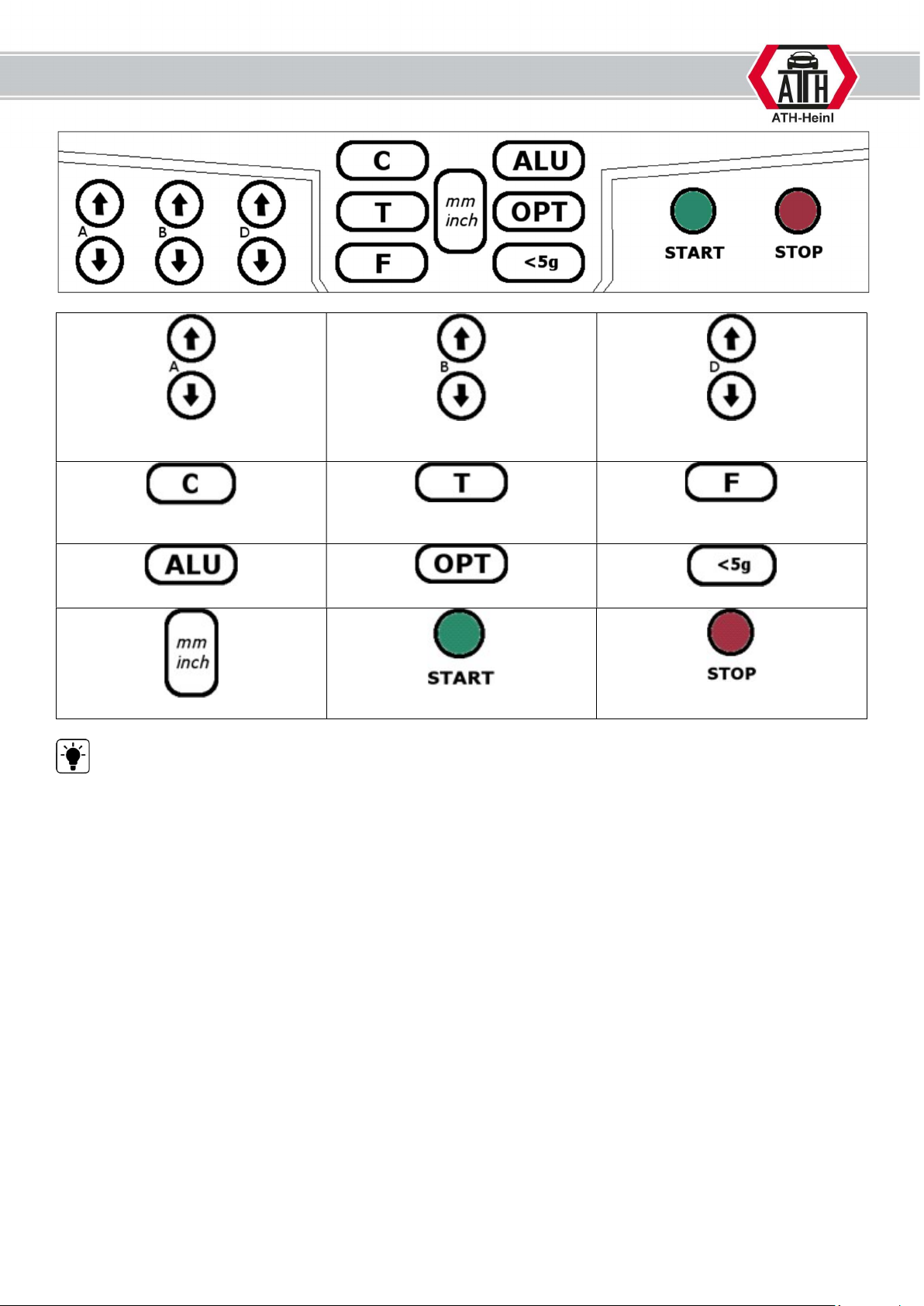
Distance between rim and
machine
Rim width
Rim diameter
Calibration button
Self test
Change between
DYNAMIC/STATIC
ALU programme selection
Optimisation programme
Display precise imbalance < 5 g
Change size entries
- Button
- Button
Only operate the buttons with your fingers. Under no circumstances should sharp objects be used.
® Copyright ATH-Heinl GmbH & Co. KG, 2019, All rights reserved / Misprints and technical changes reserved / As of: 2019-03
Manufacturer ATH-Heinl GmbH & CO.KG
- 7 -
1.3 Operation
1.3.1. Self test
After it is switched on, the device carries out a self
test and then automatically switches to “dynamic”
mode
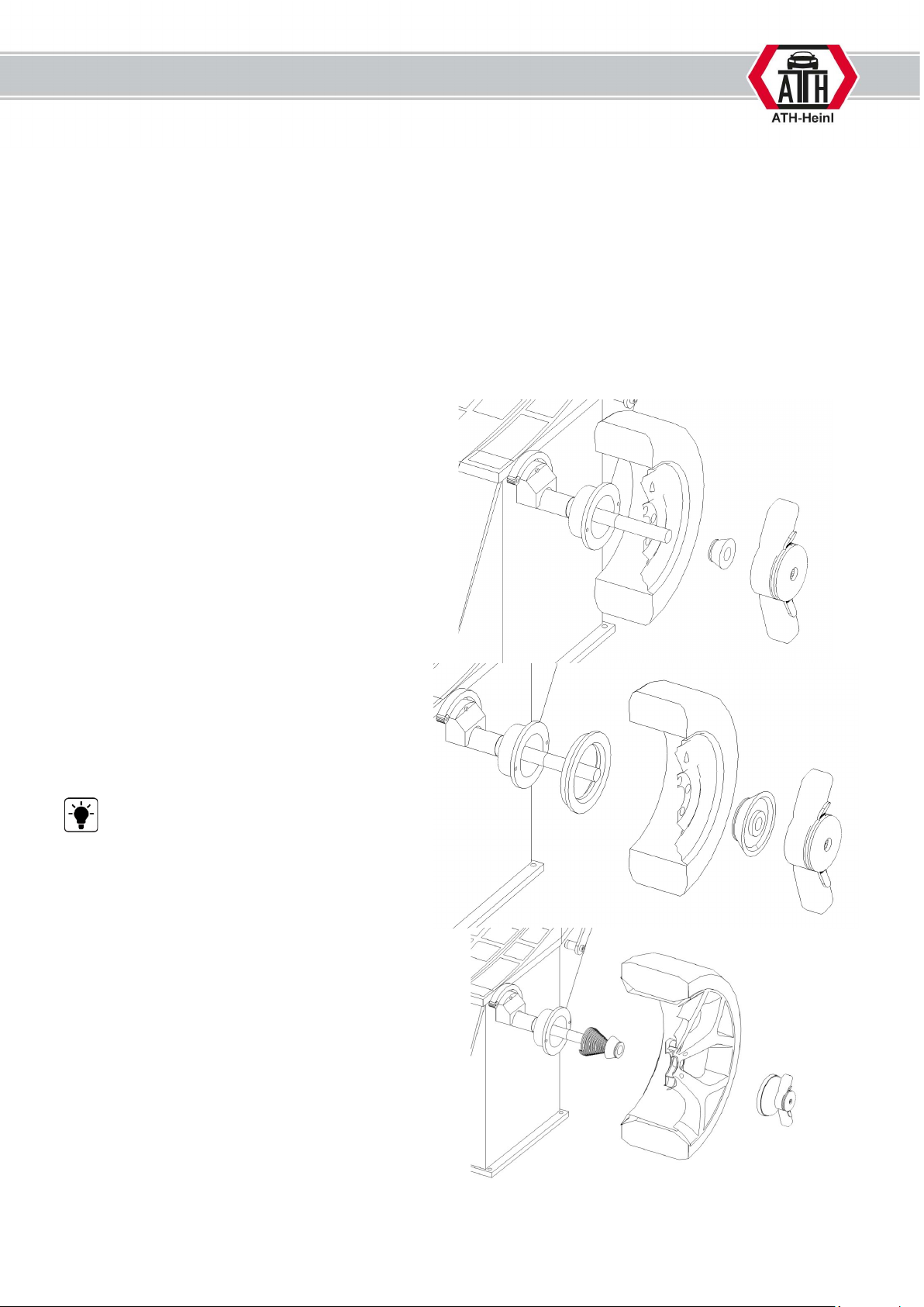
1.3.2. Wheel assembly
Select the correct cone to centre the wheel on the balancing flange.
As shown below, there are 2 easy ways to mount the wheel.
a. The first way of mounting a wheel is
shown opposite.
Using this method, the wheel rim is stretched
onto the balancing shaft from the exterior.
If you are using the largest cone, the
extension piece for the clamping cone must
also be used.
This method increases the risk of
clamping errors and is therefore only
recommended for use with steel rims.
b. When using the second method, first
position the tension springs on the
balancing shaft and then a suitable
cone. The wheel rim can be stretched
onto the balancing shaft using a
pressure hood.
® Copyright ATH-Heinl GmbH & Co. KG, 2019, All rights reserved / Misprints and technical changes reserved / As of: 2019-03
Manufacturer ATH-Heinl GmbH & CO.KG
- 8 -
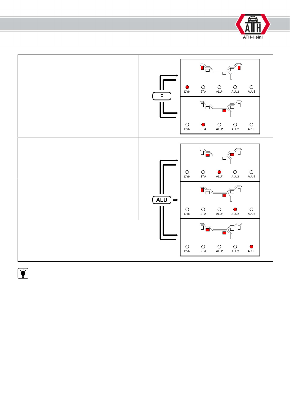
1.3.3. Selecting the balancing type
DYN
Dynamic – mode (standard):
This function calculates the radial and lateral
run-out of an aluminium or steel wheel rim.
The balancing weights are positioned on the
exterior and interior of the wheel.
STA
Static – mode:
This function calculates the radial run-out of a
steel wheel rim.
The balancing weights are positioned centrally
on the wheel rim.
ALU -1-
These functions calculate the radial and lateral
run-out of an aluminium wheel rim.
The balancing weights are positioned at a pre-
defined point.
ALU -2-
These functions calculate the radial and lateral
run-out of an aluminium wheel rim.
The balancing weights are positioned at a pre-
defined point.
ALUS
These functions calculate the radial and lateral
run-out of an aluminium wheel rim.
The balancing weights are positioned at a
location that has been pre-defined by the user.
We recommend selecting the ALUS mode to balance aluminium wheel rims. This mode not only
takes into account the exact cross section of your wheel rim, but also helps you to precisely position the
adhesive weight.
If using ALU 1, the following measurements must be observed when attaching adhesive weights:
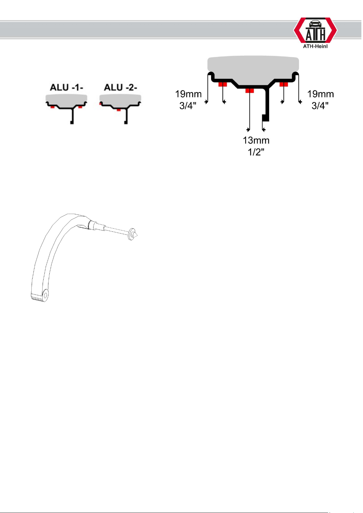
® Copyright ATH-Heinl GmbH & Co. KG, 2019, All rights reserved / Misprints and technical changes reserved / As of: 2019-03
Manufacturer ATH-Heinl GmbH & CO.KG
- 9 -
1.3.4. Entry of the tyre sizes
a) Basics:
In motorcycle mode, an optional measuring tip (+ 100 mm) must be used.
® Copyright ATH-Heinl GmbH & Co. KG, 2019, All rights reserved / Misprints and technical changes reserved / As of: 2019-03
Manufacturer ATH-Heinl GmbH & CO.KG
- 10 -
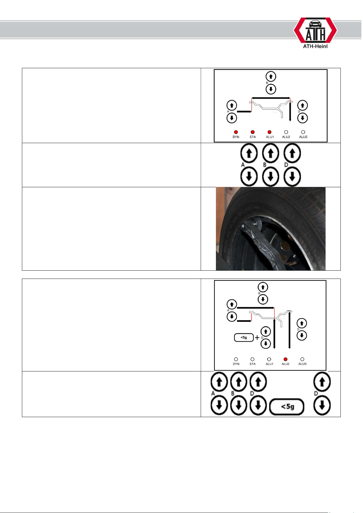
b) Wheel data and entries for calculating the imbalance:
The following data must be recorded in the DYN, STA and
ALU1 modes:
[A] Distance between wheel and machine
[B] Rim width
[D] Rim diameter
Input with the appropriate keys.
The distance is determined by positioning the gauge on
the wheel rim.
First enter the distance using [A+] / [A-].
Then enter the rim width and rim diameter using the
[B+] / [B-] and [D+]/[D-] buttons.
The following data must be recorded in ALU2 and ALUS
mode:
[A] Distance between wheel and machine
[B] Distance between the machine and the adhesive point
[D] Rim diameter
[dE] Rim diameter at the adhesive point
Input with the appropriate keys.
+
Table des matières
Autres manuels ATH-Heinl équilibreuse de roues

ATH-Heinl
ATH-Heinl W62 Manuel utilisateur

ATH-Heinl
ATH-Heinl W42 Manuel utilisateur

ATH-Heinl
ATH-Heinl W142 Manuel utilisateur

ATH-Heinl
ATH-Heinl W82 Manuel utilisateur

ATH-Heinl
ATH-Heinl W22 Manuel utilisateur

ATH-Heinl
ATH-Heinl W24 Manuel utilisateur

ATH-Heinl
ATH-Heinl ATH 800 Manuel utilisateur

ATH-Heinl
ATH-Heinl ATH 1200 Manuel utilisateur

ATH-Heinl
ATH-Heinl W102 Manuel utilisateur

ATH-Heinl
ATH-Heinl ATH W82 Manuel utilisateur


