AJAX ocBridge Plus Manuel utilisateur

ocBridge Plus User Manual
Updated March 6, 2021
Wireless sensors’ receiver ocBridge Plus is designated for connecting
compatible Ajax devices to any third party wired central unit (panel) with a help
of NC/NO contacts. Ajax system has two-way connection with the sensors
which enables it’s functioning in two modes: active mode and passive mode.
When the system is in passive mode, wireless sensors switch to power-saving
mode, which makes it possible to extend signicantly battery life.
If the receiver ocBridge Plus is connected to the wire central unit, the digital input «IN»
(wire input) MUST have connection with relay output or transistor output from the central
unit, and this output must be inverted when the central unit is being armed or disarmed.
Detailed description of connection to the central unit described in Managing the central
unit.
Functional Elements
Buy ocBridge Plus

Picture 1. ocBridge Plus wireless sensors receiver
Sensors’ handling
1. — ocBridge Plus main board
2. — terminal strip for connection to the main zones of the central unit
3. — 8 red lights indicators of the main zones
4. — mini USB connector
5. — red and green light indicators (consult the table for the description)
6. — «opening» tamper button
7. — green power supply indicator
8. — battery for backup saving
9. — IN digital input
10. — power supply switch
11. — terminal strip for connection to the central unit service zones
12. — 4 green indicators of the service zones
13. — «breakdown» tamper button (on the reverse of the main board)
14. — antennas

1. Connect the ocBridge Plus to the computer with a help of USB cable (type A–
miniUSB) through connector «4» (Picture 1). Turn on the receiver with the switch
«10» (Picture 1).
If it is the rst connection, wait until the system identify new device and install
the software drivers. If the drivers were not installed automatically, you will have
to install the driver-program vcpdriver_v1.3.1 manually. There are different
versions of this program for x86 and x64 Windows platforms.
In the archive vcpdriver_v1.3.1_setup.zip on CD you can nd two les:
VCP_V1.3.1_Setup.exe for 32-bit Windows operating systems and
VCP_V1.3.1_Setup_x64.exe — for 64-bit Windows operating systems on the CD.
Please note that if you initially install an unsuitable driver and then install the
correct one over it, ocBridge Plus will not work with the PC’s congurator
program!
If the wrong driver was installed, at rst, it is necessary to uninstall it (through
Windows programs uninstall), then reboot the computer and install the
necessary software driver. Also, .NET Framework 4 (or newer version) should be
installed. After drivers installation, launch the program «Ajax ocBridge Plus
congurator».
Consults Using conguration software of this manual provides the details about
the program «Ajax ocBridge Plus congurator» functioning. In the program
settings in «Ajax ocBridge Plus congurator» settings (menu «Connection» —
«Setting»), select COM port that is chosen by the system for the receiver
(Picture 2), click «OK» and then the «Connect» button. «Ajax ocBridge Plus
congurator» is ready to work with the ocBridge Plus receiver.
Picture 2. Selecting the COM port for connecting the receiver to the computer
Light «5» (Picture 1) indication description:
Indication Description

Green light is permanent, red light does not
blink
ocBridge Plus is in conguration mode. In
conguration, there are Pages “Radio zones” or
«Events memory» are opened. During this
period, the sensors do not receive the
responses to the alarm signals and statuses
Green — blinks once per second (before, the
green light was permanent), and the red —
blinks during 30 seconds
New radio set unit detection mode is on
The red blinks momentarily A moment when the ocBridge Plus receiver
register a new device
The green — blinks for 10 minutes and the red is
permanent;
no red light
Searching for all devices after the previously
saved PC conguration is downloaded,
system is armed;
system is disarmed
No green and red light The receiver is in in the operating mode, the
system is disarmed
Permanent red light The receiver is in operating mode, the system is
armed
Permanent green light, the red light is blinking
very fast
Radio signal is tested in order to connected
sensor or other device
Green light blinks momentarily New detectors’ polling period started, 36
seconds by default
Red/green- blinks momentarily Failure is detected
2. All devices that you want to connect to the ocBridge Plus must be registered
with a help of «Ajax ocBridge Plus congurator». In order to register the
sensors, it is necessary to create radio zones in the congurator in case of it had
not been done before. To do this select the “Radio zone” and click «Add zone»
button (Picture 3).
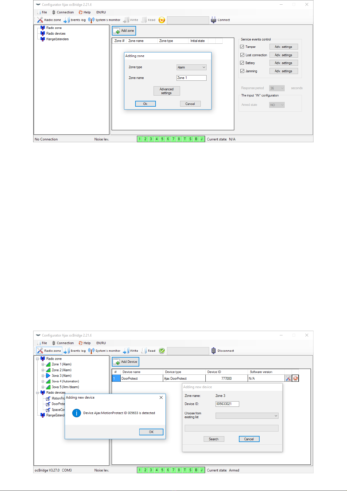
Picture 3. Adding a zone
Then, appropriate “Zone type” and settings is to be selected (consult Managing
the central unit of the present manual). To add a device chose necessary zone
and click “Add a device” button. Then, a “Adding new device” window appears
and it is necessary enter sensor’s identier (ID) applied on it below QR code,
then click the “Search” button (Picture 4).
When the search indicator bar begins to move, it is necessary to turn on the
sensor. The registration request is sent only when the sensor is being switched
on! In case of the registration fail, turn off the sensor for 5 seconds and then
turn it on again. If the sensor is on and its light blinks once per second during
one minute, it means that the sensor is not registered! The light blinks in the
same way if the sensor is deleted from the ocBridge!

Picture 4. Device registration window
3. If the sensor was mistakenly registered in a wrong zone, click on its
“Properties” button. The settings window will appear permitting to select a new
zone for the sensor (Picture 5). You can also open the detector properties menu
by clicking the corresponding button opposite the detector in the general list of
the “Radio devices” tree.
Picture 5. The sensor’s properties’ menu makes it possible to register the sensor
in the zone
When an additional wire sensor is connected to the external digital input of the
wireless sensor, in the properties activate the checkbox “Additional input”
(Picture 5). If a sensor (for example, a LeaksProtect) is designed for working 24
h, activate in the checkbox properties “24 h active”. 24 h sensors and normal
sensors should not be placed in the same zone! If necessary, adjust the sensor’s
sensitivity.
4. When the sensors are successfully registered in the security system, click the
button “Write” (Picture 4) to save sensors’ conguration data in the ocBridge
Plus receiver’s memory. When ocBridge Plus connected to the PC, click the
button “Read” (Picture 4) to read the pre-saved sensors’ conguration from the
ocBridge Plus memory.
Make sure that installation location of sensor, has a stable radio contact with the
ocBridge Plus receiver! A maximum distance of 2000 m (6552 ft) between the sensor

and the receiver is mentioned as a comparison with other devices. This distance was
found is as a result of open area tests. Connection quality and distance between the
sensor and the receiver can vary depending on installation location, walls,
compartments, bridgings, as well as the thickness and constructional material. The
signal loses a power passing through barriers. For example, distance between the
detector and receiver that divided by two concrete walls is approximately 30 m (98.4 ft).
Take into consideration, if you move the sensor even 10 cm (4 in), it is possible to
improve signicantly the quality radio signal between the sensor and the ocBridge Plus.
5. Select an appropriate place to install the sensors.
Please check the signal level of the connected devices! The radio signal test you
can nd on the page “System’s monitor” of the conguration software. To start
radio signal test press the button with antenna against the selected sensor
(Picture 6) (only when the sensors are in the operating mode and there is no red
light).
Picture 6. “System monitor” page
Picture 7. Signal level

The results of the test are shown in the conguration software (Picture 7) as 3
indication bars, and by the sensor light. The test results can be the following:
Receiver Sensor Light Emitting Diode Description
3 indication bars Lights permanently, with short breaks each 1.5
seconds Excellent signal
2 indication bars Blinks 5 times per second Medium signal
1indication bar Blinks twice per second Low signal
No bar Short ashes each 1.5 seconds No signal
Please install the sensors in the places with the signal level of 3 or 2 bars. Otherwise, the
sensor may function inconsistently.
6. The maximum number of devices that you can connect to the ocBridge Plus
depends on the polling period.
Sensors’ Quantity Polling Period
100 36 seconds and more
79 24 seconds
39 12 seconds
7. List of supported wireless detectors and devices:
DoorProtect
MotionProtect
GlassProtect
LeaksProtect
FireProtect
CombiProtect
SpaceControl

Using conguration software
1. “File” menu (Picture 8) allows to:
Picture 8. “File” menu
2. “Connection” menu (Picture 9) allows to:
Picture 9. “Connection” menu
3. The “Help“ menu (Picture 10) allows you to:
MotionProtect Plus
FireProtect Plus
save active conguration of ocBridge Plus settings in le on PC (Save
congurations to le);
upload to ocBridge Plus the settings’ conguration saved on the computer
(Open the existing conguration);
start the rmware upgrade (Firmware update);
clear all settings (Factory reset). All the data and previously saved settings
will be deleted!
select COM port for ocBridge Plus connection to the computer (Settings);
connect the ocBridge Plus to the computer (Connection);
disconnect ocBridge Plus from computer (Disconnection).

Picture. 10. “Help” menu
4. On page “Radio zones” (Picture 11) it is possible to create required the
detection zones areas required and to add there sensors and devices (consult
Sensors’ handling) and also to set the additional parameters of sensors’,
devices’ and zones functioning (consults Managing the central unit).
Picture 11. Radio zones
5. The buttons “Write” and “Read” are used for saving data in ocBridge memory
and for reading current conguration settings (Sensors’ handling).
6. “Events memory” page stores information about alarming events (Picture 12),
service events (Picture 13) and statistics tables (Picture 14). It is possible to
renew information in data logs or to clear them with “Log reset” button. The logs
contains up to 50 alarming events and 50 service events. With the button “Save
in le”, it is possible to save the events logs in xml format which can be opened
with Excel.
nd the information on the current software version;
download the help le.
Autres manuels pour ocBridge Plus
1
Ce manuel convient aux modèles suivants
1
Table des matières
Autres manuels AJAX Unité de contrôle

Manuels Unité de contrôle populaires d'autres marques

Festo
Festo Compact Performance CP-FB6-E Manuel de la liste des pièces

Elo TouchSystems
Elo TouchSystems DMS-SA19P-EXTME Manuel utilisateur

JS Automation
JS Automation MPC3034A Manuel utilisateur

JAUDT
JAUDT SW GII 6406 Series Guide rapide

Spektrum
Spektrum Air Module System Manuel utilisateur

BOC Edwards
BOC Edwards Q Series Manuel utilisateur


