
Airspan Networks ASMAX2300 Manuel utilisateur

User Manual
WiMAX Modem
Manual Version: 1.3
Manual Date: Feb. 20 2009
Software Version: R4.6.0.0-17743-v5.7.0
Software Date: Feb. 20 2009

i
CONTENTS
Chapter 1 Overview..................................................................1-1
1.1. Indoor CPE............................................................................................. 1-1
1.2. Outdoor CPE.......................................................................................... 1-2
Chapter 2 WEB-GUI.................................................................2-3
2.1. System Configuration Login.................................................................. 2-3
2.2. System Logout....................................................................................... 2-6
2.3. Account.................................................................................................. 2-7
2.4. Date........................................................................................................ 2-8
2.5. Language................................................................................................ 2-9
2.6. Scanner................................................................................................. 2-10
2.7. Authentication.......................................................................................2-11
2.8. Bridge Mode ........................................................................................ 2-13
2.9. NAT Mode ........................................................................................... 2-14
2.10. Firewall................................................................................................ 2-15
2.11. DHCP Server........................................................................................ 2-17
2.12. NATALG............................................................................................. 2-19
2.13. Port Forwarding................................................................................... 2-20
2.14. Port Trigger.......................................................................................... 2-21
2.15. DDNS................................................................................................... 2-22
2.16. TR-069................................................................................................. 2-24
2.17. SNMP................................................................................................... 2-26
2.18. Log....................................................................................................... 2-27
2.19. Upgrade................................................................................................ 2-28
2.20. Recovery.............................................................................................. 2-30
2.21. Reboot.................................................................................................. 2-31

ii
FIGURES
Figure 1-1 Indoor CPE Front Panel LED ............................................... 1-1
Figure 1-2 Outdoor CPE installation ...................................................... 1-2
Figure 2-1 Login Page ............................................................................ 2-3
Figure 2-2 WiMAX Status...................................................................... 2-4
Figure 2-3 WiMAX Status-Service Flow ............................................... 2-4
Figure 2-4 Network Status...................................................................... 2-5
Figure 2-5 Device Status......................................................................... 2-5
Figure 2-6 Logout................................................................................... 2-6
Figure 2-7 Account ................................................................................. 2-7
Figure 2-8 Date....................................................................................... 2-8
Figure 2-9 Language............................................................................... 2-9
Figure 2-10 Scanner with Bandwidth range ......................................... 2-10
Figure 2-11 Authentication....................................................................2-11
Figure 2-12 Authentication-View Certificates...................................... 2-12
Figure 2-13 Bridge Mode...................................................................... 2-13
Figure 2-14 NAT Mode......................................................................... 2-14
Figure 2-15 Firewall ............................................................................. 2-15
Figure 2-16 Firewall Filter.................................................................... 2-16
Figure 2-17 DHCP Server Enabled....................................................... 2-17
Figure 2-18 DHCP Server Disabled...................................................... 2-18
Figure 2-19 NAT ALG.......................................................................... 2-19
Figure 2-20 Port Forwarding ................................................................ 2-20
Figure 2-21 Port Trigger ....................................................................... 2-21
Figure 2-22 DDNS Enabled.................................................................. 2-22
Figure 2-23 DDNS Disabled................................................................. 2-23
Figure 2-24 TR-069 .............................................................................. 2-25
Figure 2-25 TR-069-Certificate File Upload........................................ 2-25
Figure 2-26 SNMP enabled................................................................... 2-26
Figure 2-27 SNMP disabled.................................................................. 2-26
Figure 2-28 Log .................................................................................... 2-27
Figure 2-29 Web/FTP Upgrade............................................................. 2-28
Figure 2-30 Web Upgrade Summary.................................................... 2-29
Figure 2-31 TFTP Upgrade................................................................... 2-29
Figure 2-32 Recovery ........................................................................... 2-30
Figure 2-33 Reboot Button ................................................................... 2-31

iii
Figure 2-34 Reboot Confirmation......................................................... 2-32

1-1
Chapter 1 Overview
This chapter describes the panel function and installation procedure for the
CPE.
1.1. Indoor CPE
Front Panel LED
Power LED: ON: power on OFF: power fail
LAN LED: ON: connect OFF: disconnect Blinking: data transmit
When the CPE powers on, the LED indicates the CPE states as follow.
Only Red LED is Blinking: synchronization
Only Yellow LED is Blinking: authentication
Only Green LED is Blinking: DHCP client negotiation
After the CPE has connected to the base station, the signal strength LED are
defined as follow.
Only Red LED is ON: the signal is weak. (CINR<8dB)
Yellow LED is ON: the signal strength is medium. (8dB≤CINR<15dB)
Green LED is ON: the signal strength is good. (15dB≤CINR)
Figure 1-1 Indoor CPE Front Panel LED
1-2
Rear Panel
Power jack: DC 12V / 1.5A
LAN port: 10/100Base-TX
Reset button: To reboot the CPE
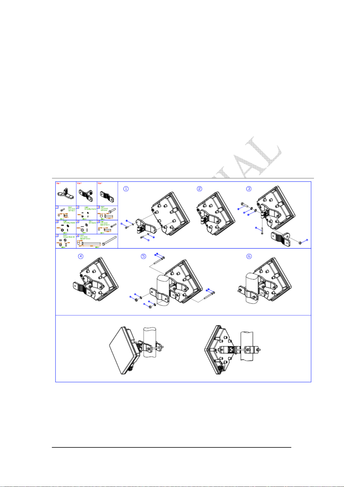
1.2. Outdoor CPE
Power Injector – Power Over Ethernet 802.3af compliant
LAN port: 10/100Base-TX
Figure 1-2 Outdoor CPE installation

2-3
Chapter 2 WEB-GUI
This chapter describes how to configure the CPE in order to connect to the base
station.
2.1. System Configuration Login
The CPE will enable a DHCP server by default. Computers or network devices
connected to its LAN side can get IP address automatically from CPE. If you disable
CPE’s DHCP server by yourself, set the IP address, net mask, and gateway as
following.
IP address: 10.1.1.x, 1 ≤x ≤253
Netmask: 255.255.255.0
Gateway: 10.1.1.254
Connect to http://10.1.1.254/ with a browser, and you will see a webpage such as the
one shown in Figure 2-1. The administrator username and password are as shown
below:
Username: admin
Password: admin
WiMAX CPE also support multi-level user login. Please contact with us to define
multi-user features.
Figure 2-1 Login Page

2-4
If there is no error, the user can login into the Status Page, and WiMAX Status,
Network Status, and Device Status are as shown in Figure 2-2, Figure 2-3, Figure 2-4,
and Figure 2-5.
Figure 2-2 WiMAX Status
Figure 2-3 WiMAX Status-Service Flow

2-5
Figure 2-4 Network Status
Figure 2-5 Device Status

2-6
2.2. System Logout
Press the “Logout” button as shown in Figure 2-6 to logout of the system and
go back to the “Login” page as shown in Figure 2-1.
Figure 2-6 Logout
Table des matières
Manuels Modem populaires d'autres marques

Davicom
Davicom DM562AP Manuel utilisateur

EpiValley
EpiValley TATA indicom SXC-1080 Manuel utilisateur

Zte
Zte WiMAX Manuel utilisateur

Intelimax
Intelimax MA-2060 Manuel utilisateur

SMC Networks
SMC Networks D3CM1604V Manuel d'utilisation et d'entretien

Telstra
Telstra Wi-Fi 4G Advanced Pro X Manuel utilisateur


US Robotics
US Robotics 3453C Manuel utilisateur

MaxTech
MaxTech Plug & Play Internal Voice/FAX/Data/SVD... Manuel utilisateur

Zte
Zte MF823 Manuel utilisateur

Four-Faith
Four-Faith F1403 Manuel utilisateur

Sierra Wireless
Sierra Wireless AIRLINK MP595W Manuel utilisateur

Gemtek
Gemtek WiMAX WIXFBR-103 Manuel utilisateur