AFINIA LABEL DLF L Series Manuel utilisateur

1
DLF Training
Contents
DLF Training .........................................................................................................................................................1
DLF-220L.......................................................................................................................................................3
DLF-350L.......................................................................................................................................................3
1. Installation ...............................................................................................................................................4
Uncrating......................................................................................................................................................4
Leveling ........................................................................................................................................................4
Waste Compactor Installation .....................................................................................................................5
Dongle and USB Connections.......................................................................................................................8
DLF Software Installation .............................................................................................................................9
2. Artwork ................................................................................................................................................. 12
Artwork Layout ......................................................................................................................................... 12
Registration Mark (Blackmark) Requirements.......................................................................................... 12
Save the Master File.................................................................................................................................. 15
Save the Print File ..................................................................................................................................... 16
Save the Cut File........................................................................................................................................ 16
Special Cut Line for perforations............................................................................................................... 16
3. Loading Media and Laminate................................................................................................................ 17
Loading Media........................................................................................................................................... 17
Loading Laminate...................................................................................................................................... 19
4. Loading Cutter....................................................................................................................................... 20
5. Blade Exposure...................................................................................................................................... 21
6. Software Operation............................................................................................................................... 21
Positioning the reg mark in the software image....................................................................................... 22
Setting the cut parameters ....................................................................................................................... 23
Cut Test ..................................................................................................................................................... 24
Start the cut job ........................................................................................................................................ 25
7. Waste Removal and Rewinding ............................................................................................................ 26
8. Slitting ................................................................................................................................................... 29

2
Adding or Removing Slitter Blade Holders................................................................................................ 30
9. Output/Waste Roll Removal ................................................................................................................. 31
10. Tension Arm Calibration ................................................................................................................... 32
11. Advanced/Settings Features ............................................................................................................. 33
12. Maintenance ..................................................................................................................................... 36
General Cleaning....................................................................................................................................... 36
Lubrication ................................................................................................................................................ 36
Consumable Replacement ........................................................................................................................ 37
13. Troubleshooting................................................................................................................................ 38
3
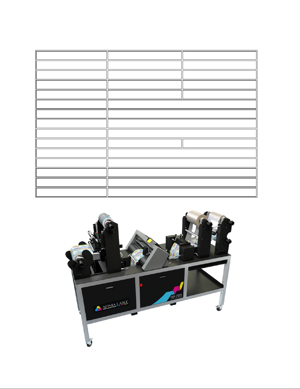
DLF L Series
DLF-220L
DLF-350L
Input / Output Roll Diameter
9.84” (250 mm)
9.84” (250 mm)
Minimum Web Width
4.33” (110 mm)
4.33” (110 mm)
Maximum Web Width
8.86” (225 mm)
14” (355 mm)
Maximum Cutting Width
7.87” (200 mm)
13” (330 mm)
Minimum Slitting Width
0.75” (19 mm)
Minimum Label Length
0.39” (10 mm)
Maximum Label Length
15” (381 mm)
Lamination Module
YES
Number of Slitting Blades
up to 8
up to 13
Minimum Media Thickness
0.01″ (0.25 mm) (10 mil)
Maximum Cutting Speed
24 in/s (600 mm/s) in all directions
Roll Core Size
3” (76 mm)
Agency Certifications
CE, FCC, RoHS
Warranty
One Year Parts and Labor. Usage Limitation may apply

4
1. Installation
Team Lifting is required when moving any of the DLF Series Finishers!
Uncrating
1. Remove screws from all clips on the front of the crate
a. The top, left, and right sides will have 1 screw on
each side of the clip
b. The bottom clips will only have screws on the
front, not on the bottom of the crate
2. Remove the clips using a flat-blade screwdriver
3. Remove all packing materials from inside the crate
4. The DLF will be mounted on top of two wooden stands inside the crate. You will need THREE
PEOPLE to safely remove the DLF from the crate.
5. Partially slide the DLF on top of the two wooden stands until there is room on the sides of the DLF
for a person on each side to have a hand hold
6. Carefully slide the DLF the rest of the way out of the crate and lower the DLF-220L to the floor
7. Remove stretch wrap, wire ties, foam, and bag from around the cutter
Leveling
Although leveling is not critical, the DLF Series finishers should be operated in as level of an environment as
possible.

5
Waste Compactor Installation
The DLF-220L units come with a waste compactor assembly that needs to be installed once the unit is
uncrated. The assembly is installed due to shipping onto the Laminate Mandrel Tower of the unit and looks
like the below images when removed from the crate.

6
The assembly is held temporarily with 4 Philips screws.
Once the assembly is removed, it is to be installed above the Waste Take-up Mandrel as shown below.

7
In this location on the Waste Take-up Mandrel Tower there are 10 Philips screws pre-installed that need to
be removed. Once the 10 screws are removed, you position the waste compactor onto the Waste Take-up
Mandrel Tower and reinstall the screws.
Once installed, the Waste Compactor Assembly can be locked in the up postion using the lock pin on the
side of it as shown below.

8
Dongle and USB Connections
Verify power and USB connections to cutter, PC, and dongle is in place
DLF-220L
a. Power connection is located behind the left front panel, behind the center-left front support
beam. The leftmost side panel on the operator side can be removed to view this plug
location.
b. USB connections and dongle are located behind the center front panel

9
DLF Software Installation
The DLF-Software needs to be installed on a Windows computer. You will want to disable any additional
webcams/imaging devices on the computer so the Cutter’s Webcam is properly detected by the software.
Run the installer BEFORE turning on the DLF and plugging into the computer.
1. Open the Setup DLF-Software X.X.X (X referring to version number)
2. Once opened you will be presented with a DLF-Software Install Wizard, click Next
3. Next screen shows a change-log for the software. Click Next again
4. Next screen will show the default install directory for the DLF-Software (C:\DLF-Software\). It is
recommended you don’t change this. Click Next.

10
5. Next screen is a confirmation window that the installer is ready to proceed. Click Next.
6. The installer will start running the installation process and provide a progress bar. Once the progress
bar is finished a second window will pop up, Device Driver Installation Wizard. Click Next on the
Device Driver Installation Wizard Window. The driver will install and provide a confirmation that the
driver installed properly. Click Finish
7. After Clicking Finish on the Device Driver Installation Wizard, another window will pop up for the
Graphtec Cutting Plotter Driver. Click OK to start the process. The next window will provide a
prompt to confirm you have not plugged in/turned on the cutter on the DLF before proceeding to
the next step. Click Next.
Ce manuel convient aux modèles suivants
2
Table des matières
Autres manuels AFINIA LABEL Étiqueteuse

AFINIA LABEL
AFINIA LABEL DLP-2000 Manuel utilisateur

AFINIA LABEL
AFINIA LABEL Afinia 502 Fiche technique

AFINIA LABEL
AFINIA LABEL Afinia L501 Manuel utilisateur

AFINIA LABEL
AFINIA LABEL AP200 Manuel utilisateur

AFINIA LABEL
AFINIA LABEL L801 Manuel de référence

AFINIA LABEL
AFINIA LABEL Mini DLF Series Manuel utilisateur

AFINIA LABEL
AFINIA LABEL Afinia L501 Fiche technique

AFINIA LABEL
AFINIA LABEL A200 Manuel utilisateur

AFINIA LABEL
AFINIA LABEL L301 Fiche technique

AFINIA LABEL
AFINIA LABEL L901 Manuel utilisateur


