
ADEEPT Super Starter Manuel utilisateur


Preface
Adeept is a technical service team of open source software and hardware.
Dedicated to applying the Internet and the latest industrial technology in open
source area, we strive to provide best hardware support and software service for
general makers and electronic enthusiasts around the world. We aim to create
infinite possibilities with sharing. No matter what field you are in, we can lead you
into the electronic world and bring your ideas into reality.
This is an entry-level learning kit for Arduino. Some common electronic
components and sensors are included. Through the learning, you will get a better
understanding of Arduino, and be able to make fascinating works based on
Arduino.
If you have any problems for learning, please contact us at support@adeept.com.
We will do our best to help you solve the problem.

Component List
1x Adeept UNO Board(Arduino UNO)
1x DC Motor
1x L9110 motor driver
1x LCD1602
1x Dot-matrix Display
1x 7-Segment Display
1x NE555 timer
2x 74HC595
1x Active buzzer
1x Photoresistance
1x Tilt Switch
2x Switch
1x RGB LED
8x Red LED
4x Green LED
4x Yellow LED
4x Blue LED
16x Resistor(220Ω)
10x Resistor(1 kΩ)
5x Resistor(10 kΩ)
5x Capacitor(104)
2x Capacitor(10uF)
4x Button(large)
8x Button(small)
1x Button cap(red)
1x Button cap(white)
2x Button cap(blue)
2x NPN Transistor(8050)
2x PNP Transistor(8550)
2x Potentiometer(10KΩ)
1x A battery holder
1x Breadboard
1x USB Cable
40x Male to Male Jumper Wires
8x Male to Female Jumper Wires
1x Header(40pin)
1x Band Resistor Card
1x Project Box

Content
About Arduino.......................................................................................................................... - 1 -
Lesson 1 Blinking LED........................................................................................................... - 2 -
Lesson 2 Buzzer...................................................................................................................... - 6 -
Lesson 3 Controlling an LED with a button.................................................................. - 10 -
Lesson 4 Tilt Switch............................................................................................................. - 15 -
Lesson 5 LED Flowing Lights ............................................................................................ - 18 -
Lesson 6 Breathing LED..................................................................................................... - 21 -
Lesson 7 Controlling a RGB LED by PWM..................................................................... - 25 -
Lesson 8 7-segment display ............................................................................................. - 28 -
Lesson 9 Dot-matrix display ............................................................................................. - 32 -
Lesson 10 LCD1602............................................................................................................. - 37 -
Lesson 11 Photoresistor..................................................................................................... - 41 -
Lesson 12 Serial Port........................................................................................................... - 44 -
Lesson 13 Frequency meter ............................................................................................. - 49 -
Lesson 14 A Simple Voltmeter......................................................................................... - 54 -
Lesson 15 DC motor............................................................................................................ - 57 -

- 1 -
About Arduino
What is Arduino?
Arduino is an open-source electronics platform based on easy-to-use
hardware and software. It's intended for anyone making interactive projects.
ARDUINO BOARD
Arduino senses the environment by receiving inputs from many sensors, and
affects its surroundings by controlling lights, motors, and other actuators.
ARDUINO SOFTWARE
You can tell your Arduino what to do by writing code in the Arduino
programming language and using the Arduino development environment.
Before the development of Arduino program, the first thing you have to do is to
install Arduino IDE software. The software provides you with the basic
development environment that is required for developing Arduino program.
You need the following URL to download Arduino IDE:
http://www.arduino.cc/en/Main/Software
For different operating system platforms, the way of using Arduino IDE is
different. Please refer to the following links:
Windows User:http://www.arduino.cc/en/Guide/Windows
Mac OS X User:http://www.arduino.cc/en/Guide/MacOSX
Linux User:http://playground.arduino.cc/Learning/Linux
For more detailed information about Arduino IDE, please refer to the following
link:
http://www.arduino.cc/en/Guide/HomePage

- 2 -
Lesson 1 Blinking LED
Overview
In this tutorial, we will start the journey of learning Arduino UNO. In the first
lesson, we will learn how to make a LED blinking.
Requirement
- 1* Arduino UNO
- 1* USB Cable
- 1* 220ΩResistor
- 1* LED
- 1* Breadboard
- 2* Jumper Wires
Principle
In this lesson, we will program the Arduino's GPIO output high(+5V) and low
level(0V), and then make the LED which is connected to the Arduino’s GPIO
flicker with a certain frequency.
1. What is the LED?
The LED is the abbreviation of light emitting diode. It is usually made of
gallium arsenide, gallium phosphide semiconductor materials. The LED has
two electrodes, a positive electrode and a negative electrode, it will light only
when a forward current passes, and it can be red, blue, green or yellow light,
etc. The color of light depends on the materials it was made.
In general, the drive current for LED is 5-20mA. Therefore, in reality it usually
needs an extra resistor for current limitation so as to protect the LED.
2. What is the resistor?
The main function of the resistor is to limit current. In the circuit, the character
‘R’represents resistor, and the unit of resistor is ohm(Ω).
The band resistor is used in this experiment. A band resistor is one whose
surface is coated with some particular color through which the resistance can
be identified directly.
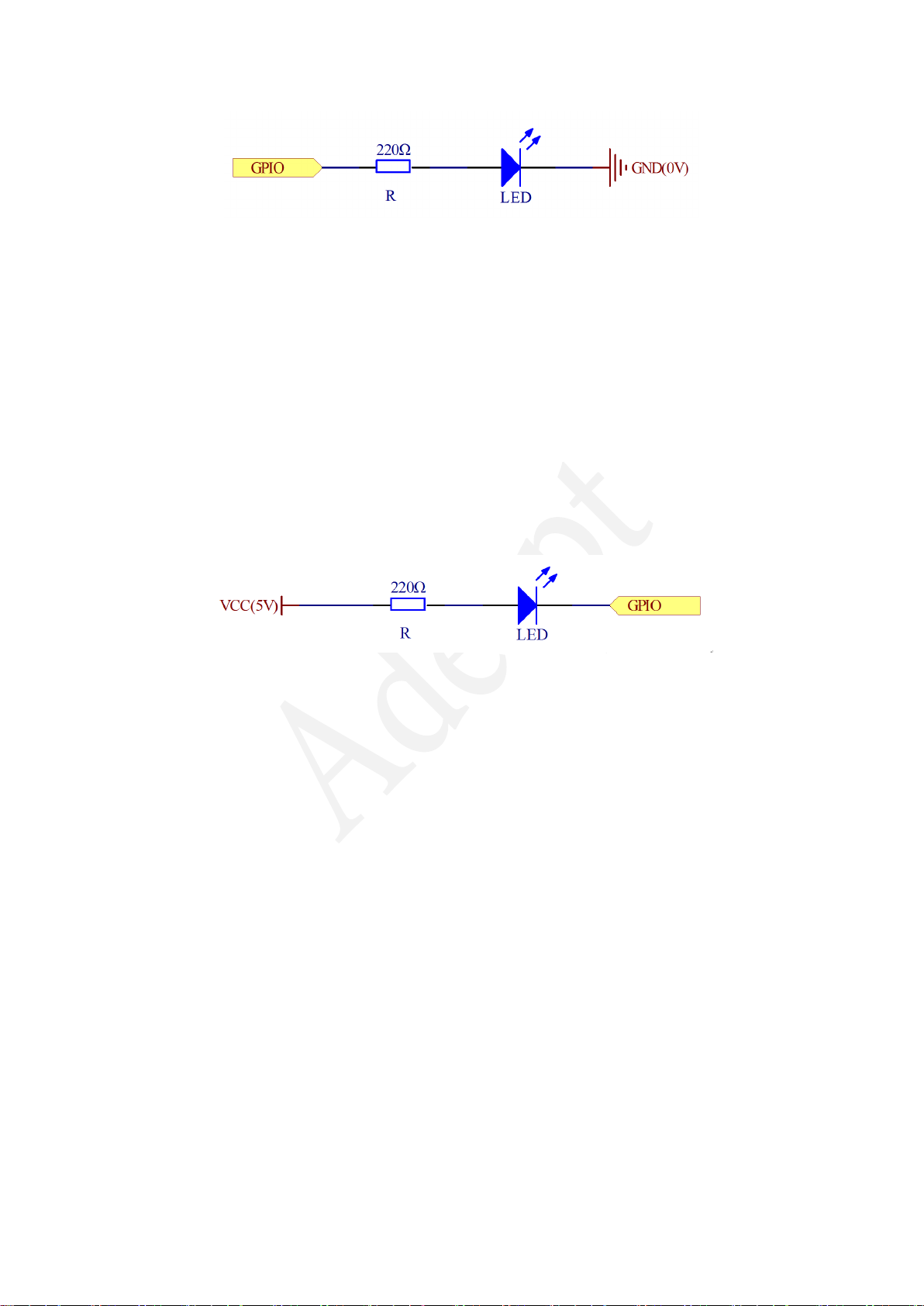
There are two methods for connecting LED to Arduino’s GPIO:
①
- 3 -
As shown in the schematic diagram above, the anode of LED is connected to
Arduino’s GPIO via a resistor, and the cathode of LED is connected to the
ground(GND). When the GPIO output high level, the LED is on; when the GPIO
output low level, the LED is off.
The size of the current-limiting resistor is calculated as follows: 5~20mA
current is required to make an LED on, and the out put voltage of the Arduino
UNO’s GPIO is 5V, so we can get the resistance:
R = U / I = 5V / (5~20mA) = 250Ω~1KΩ
Since the LED has a certain resistance, thus we choose a 220ohm resistor.
②
As shown in the schematic diagram above, the anode of LED is connected to
VCC(+5V), and the cathode of LED is connected to the Arduino’s GPIO. When
the GPIO output low level, the LED is on; when the GPIO output high level, the
LED is off.
The experiment is based on method ①, we select Arduino's D8 pin to control
the LED. When the Arduino’s D8 pin is programmed to output high level, then
the LED will be on, next delay for the amount of time, and then programmed
the D8 pin to low level to make the LED off. Continue to perform the above
process, you can get a blinking LED.
3. Key functions:
●setup()
The setup() function is called when a sketch starts. Use it to initialize variables,
pin modes, start using libraries, etc. The setup function will only run once,
after each powerup or reset of the Arduino board.
●loop()
After creating a setup() function, which initializes and sets the initial values,
the loop() function does precisely what its name suggests, and loops

- 4 -
consecutively, allowing your program to change and respond. Use it to actively
control the Arduino board.
●pinMode()
Configures the specified pin to behave either as an input or an output.
As of Arduino 1.0.1, it is possible to enable the internal pullup resistors with
the mode INPUT_PULLUP. Additionally, the INPUT mode explicitly disables the
internal pullups.
●digitalWrite()
Write a HIGH or a LOW value to a digital pin.
If the pin has been configured as an OUTPUT with pinMode(), its voltage will be
set to the corresponding value: 5V (or 3.3V on 3.3V boards) for HIGH, 0V
(ground) for LOW.
If the pin is configured as an INPUT, digitalWrite() will enable (HIGH) or disable
(LOW) the internal pullup on the input pin. It is recommended to set the
pinMode() to INPUT_PULLUP to enable the internal pull-up resistor.
●delay()
Pauses the program for the amount of time (in miliseconds) specified as
parameter. (There are 1000 milliseconds in a second.)
Procedures
1. Build the circuit

- 5 -
2. Program
/***********************************************************
File name: 01_blinkingLed.ino
Description: Lit LED, let LED blinks.
Website: www.adeept.com
E-mail: [email protected]
Author: Tom
Date: 2015/05/02
***********************************************************/
int ledPin=8;//definition digital 8 pins as pin to control the LED
void setup()
{
pinMode(ledPin,OUTPUT); //Set the digital 8 port mode, OUTPUT:
Output mode
}
void loop()
{
digitalWrite(ledPin,HIGH); //HIGH is set to about 5V PIN8
delay(1000); //Set the delay time, 1000 = 1S
digitalWrite(ledPin,LOW); //LOW is set to about 5V PIN8
delay(1000); //Set the delay time, 1000 = 1S
}
3. Compile the program and upload to Arduino UNO board
Now, you can see the LED is blinking.

- 6 -
Lesson 2 Buzzer
Overview
In this lesson, we will learn how to program the Arduino to make an active
buzzer sound.
Requirement
- 1* Arduino UNO
- 1* USB cable
- 1* Active buzzer
- 1* 1 kΩResistor
- 1* NPN Transistor (S8050)
- 1* Breadboard
- Several Jumper wires
Principle
A buzzer or beeper is an audio signaling device. As a type of electronic buzzer
with integrated structure, which use DC power supply, are widely used in
computers, printers, photocopiers, alarms, electronic toys, automotive
electronic equipments, telephones, timers and other electronic products for
voice devices. Buzzers can be categorized as active and passive buzzers (See
the following pictures).
When you place the pins of buzzers upward, you can see that two buzzers are
different, the buzzer that green circuit board exposed is the passive buzzer.
In this study, the buzzer we used is active buzzer. Active buzzer will sound as
long as the power supply. We can program to make the Arduino output
alternating high and low level, so that the buzzer sounds.
Autres manuels pour Super Starter
2
Table des matières
Autres manuels ADEEPT Équipement pédagogique


Manuels Équipement pédagogique populaires d'autres marques



fischertechnik
fischertechnik STEM Coding Pro Manuel utilisateur

Experia
Experia IRiS Light Wand Manuel utilisateur

Pitsco Education
Pitsco Education FLO Manuel utilisateur

Sphero
Sphero RVR RV01 Manuel utilisateur

Limbs & Things
Limbs & Things 60905 Manuel utilisateur

JP
JP TURN Connect T101 Manuel utilisateur

TruCorp
TruCorp AirSim Advance Manuel utilisateur

LeapFrog
LeapFrog Mr. Pencil's Scribble, Write & Read Manuel utilisateur

ScienTECH
ScienTECH 2261 Manuel utilisateur

Rompa
Rompa 20019 Manuel utilisateur

Duinotech
Duinotech XC4322 Manuel utilisateur

Enabling Devices
Enabling Devices Spinning Light Show Manuel utilisateur