
ZKTeco TS200 Series Manuel utilisateur

TS200 Series Tripod Turnstile User Manual
P a g e |1Copyright©2020 ZKTECO CO., LTD. All rights reserved.
Thank you for choosing our product. Please read the instructions
carefully before operation. Follow these instructions to ensure that the
product is functioning properly. The images shown in this manual are
for illustrative purposes only.

TS200 Series Tripod Turnstile User Manual
P a g e |1
About the Manual
This manual introduces the operations of TS200 Series Tripod Turnstile product.
All figures displayed are for illustration purposes only. Figures in this manual may not be exactly
consistent with the actual products.

TS200 Series Tripod Turnstile User Manual
P a g e |2
Document Conventions
Conventions used in this manual are listed below:
GUI Conventions
For Software
Convention
Description
Bold font
Used to identify software interface names e.g. OK,Confirm,Cancel
>
Multi-level menus are separated by these brackets. For example, File > Create >
Folder.
For Device
Convention
Description
< >
Button or key names for devices. For example, press <OK>
[ ]
Window names, menu items, data table, and field names are inside square
brackets. For example, pop up the [New User] window
/
Multi-level menus are separated by forwarding slashes. For example,
[File/Create/Folder].
Symbols
Convention
Description
This implies about the notice or pays attention to, in the manual
The general information which helps in performing the operations faster
The information which is significant
Care taken to avoid danger or mistakes
The statement or event that warns of something or that serves as a
cautionary example.

TS200 Series Tripod Turnstile User Manual
P a g e |3
Table of Contents
1 TECHNICAL SPECIFICATIONS................................................................................................................ 4
2 UNPACKING AND TESTING THE TRIPOD TURNSTILE.....................................................................5
ARM INSTALLATION.................................................................................................................................................... 5
POWER-ON TEST BEFORE INSTALLATION......................................................................................................................5
3 EQUIPMENT INSTALLATION................................................................................................................. 6
INSTALLATION CONDITIONS........................................................................................................................................ 6
CABLING.....................................................................................................................................................................7
INSTALLATION.............................................................................................................................................................8
4 CABLE DIAGRAM......................................................................................................................................9
FUNCTION DESCRIPTION OF THE TURNSTILE CONTROL BOARD.................................................................................... 9
CONNECTION DIAGRAM OF THE ACCESS CONTROLLER.............................................................................................. 10
DIP K1 SWITCH CONFIGURATION.............................................................................................................................10
4.3.1 SETTING THE TURNSTILE OPENING DURATION........................................................................................................ 10
4.3.2 DIRECTION INDICATOR..................................................................................................................................................11
4.3.3 CONTINUE PASSING FUNCTION.................................................................................................................................. 11
4.3.4 ALARM FUNCTION (OPTIONAL)................................................................................................................................... 11
5 EQUIPMENT PRECAUTIONS AND MAINTENANCE........................................................................12
PRECAUTIONS...........................................................................................................................................................12
MAINTENANCE......................................................................................................................................................... 13
6 TROUBLESHOOTING............................................................................................................................. 14
ATTACHMENT 1 FACTORY SETTINGS.......................................................................................................15
ATTACHMENT 2 CONNECTION DIAGRAM OF CONTROL BOARD AND ACCESS CONTROL
PANEL............................................................................................................................................................... 16
TS200 Series Tripod Turnstile User Manual
P a g e |4
Please read this document carefully before installation and using the device.
1Technical Specifications
Input Voltage
AC 100~120V
/200~240V,
50Hz /60Hz
Arm Length (mm)
500
Operating Environment
Indoor and
Outdoor
(shelter)
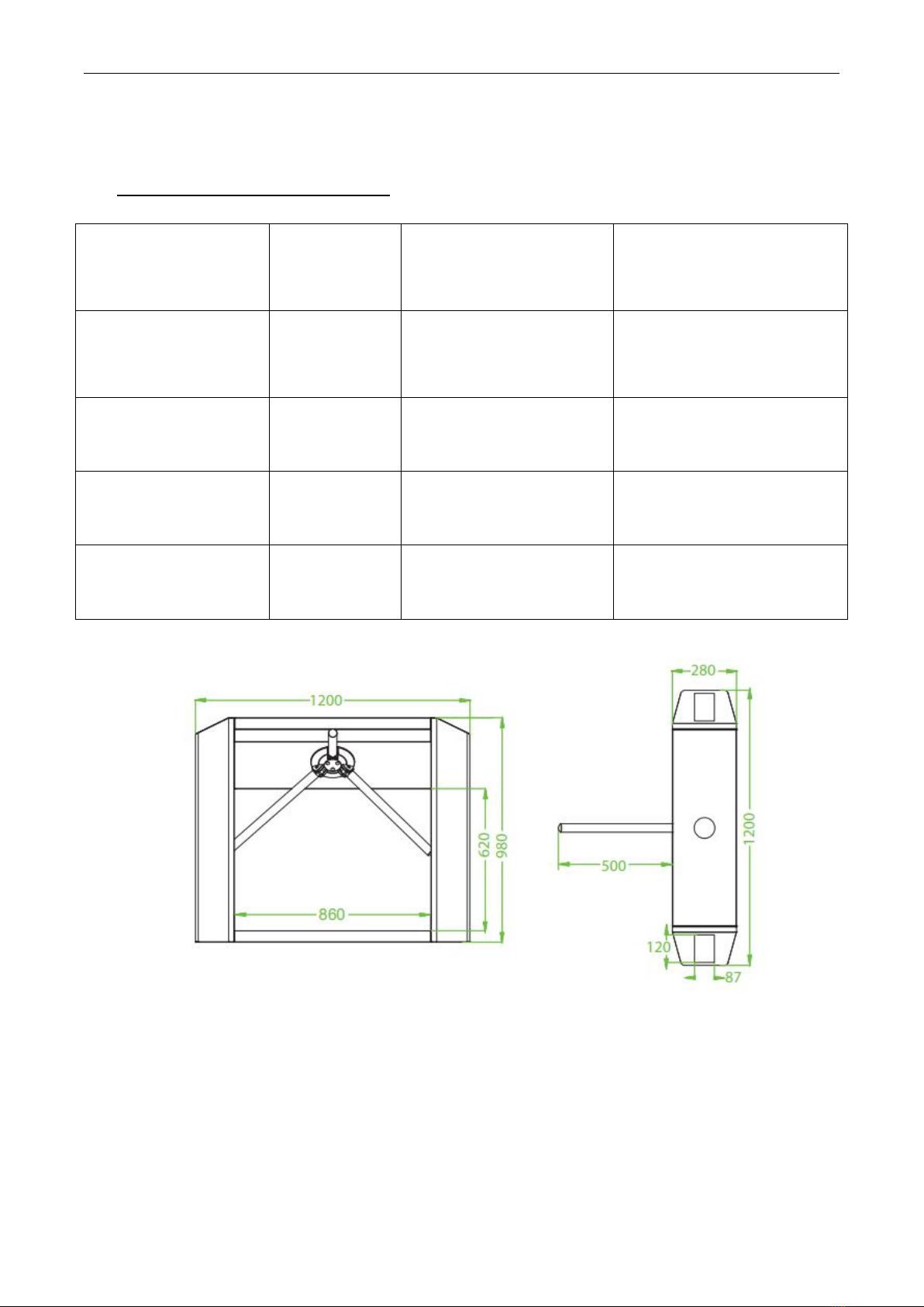
Dimension(mm) (Figure 1)
L = 1200, W = 280, H = 980
Operating Temperature
-28ºC ~ 60ºC
Package Size (mm)
L = 1275, W = 370, H = 1063
Operating Humidity
5% ~ 85%
Flow Rate
Max 30 passages / minute
Input Control Signal
Dry contact
Rated Power
18 W
Figure 1
TS200 Series Tripod Turnstile User Manual
P a g e |5
2Unpacking and Testing the Tripod Turnstile
Arm Installation
In order to prevent the arm from damaging during transportation, the arm will not be initially
installed to the devices.
Installation procedure
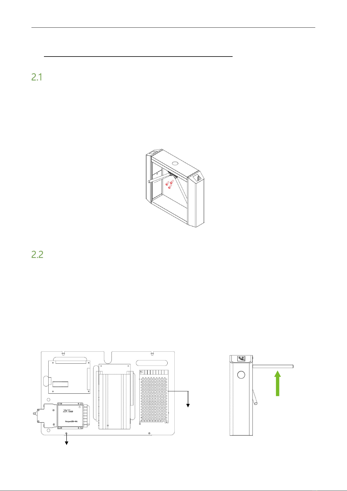
Put the arm kit into the hole of cabinet; make sure the screw holes match with mechanism core, then
tighten 3 hex screws, as shown in Figure 2-1.
Figure 2-1
Power-on Test before Installation
1. Please make sure that the power requirements are strictly met to avoid permanent damages to
the unit. Input voltage: AC 100~120V /200~240V.
Note: The tripod turnstile must be connected to the ground (earth).
2. Power on and wait 30s for the tripod turnstile to finish the self-check program.
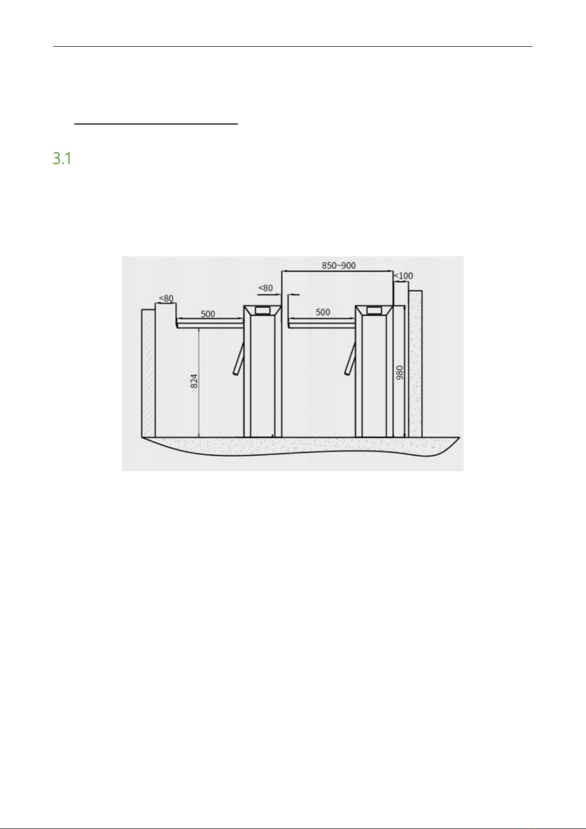
3. Lift the arms manually, as shown in Figure 2-2.
4. Check whether the tripod turnstile and the LED indicators work properly.
If there is any problem, please contact the supplier.
There is a power
switch in the side
direction of this
power supply.
Earth wiring terminal
Lift upwards
TS200 Series Tripod Turnstile User Manual
P a g e |6
Figure 2-2
3Equipment Installation
Installation Conditions
The equipment must be installed on concrete ground, ensuring that expansion bolts can be secured
firmly.
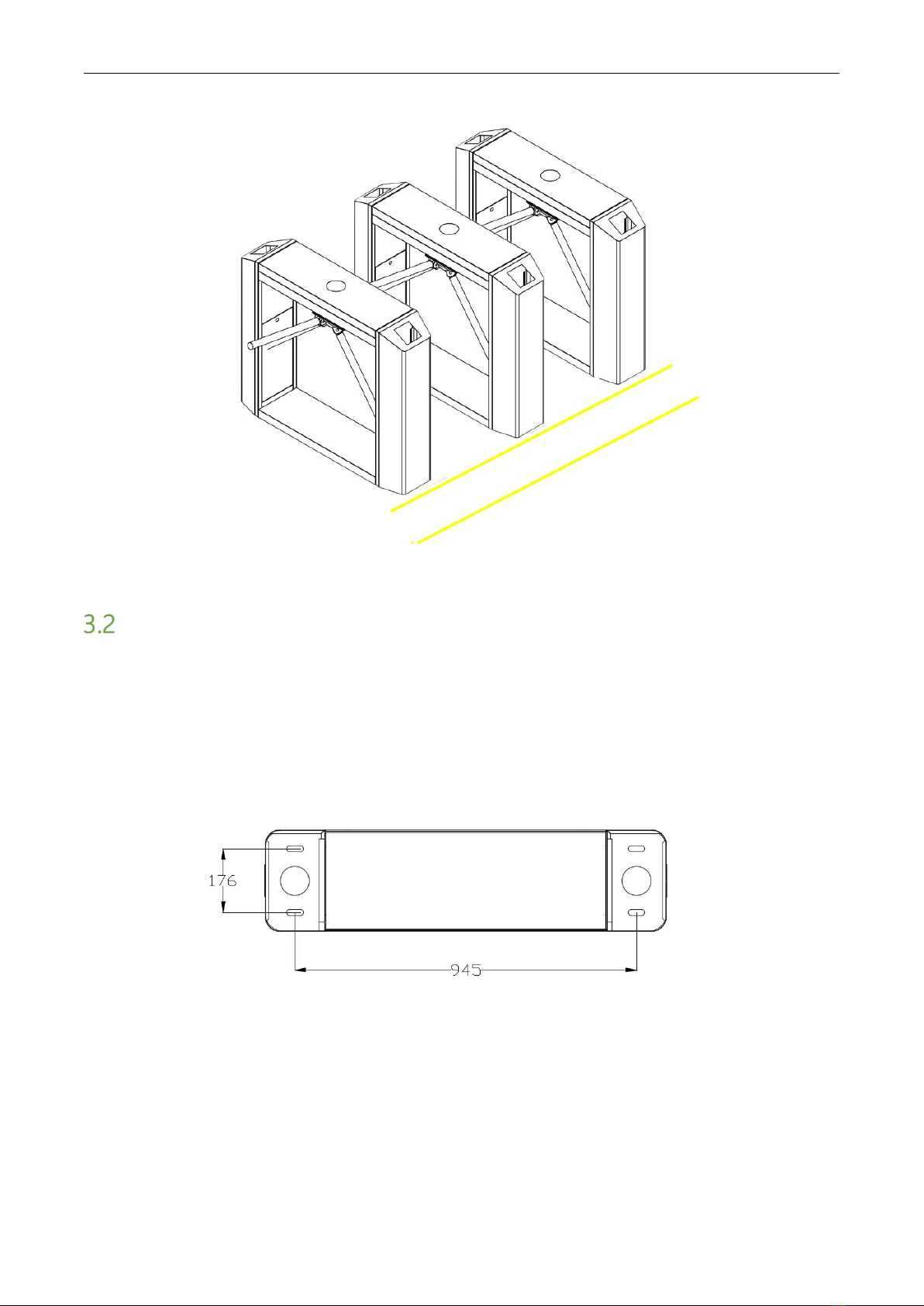
You are suggested to install an assistant framework or fence to form a passageway, as shown in
Figure 3-1.
Figure 3-1
Notes:
1. When installing the tripod turnstile against the wall, please reserve a distance of at least 100 mm
in order to open the cover for future adjustment and maintenance.
2. The spare space from the end of the arm shall not be greater than 80 mm (see Figure 3-1).
3. You are also recommended to set a warning line for card swiping (see Figure 3-2). The warning
line prompts users to swipe cards in a particular area, which would greatly reduce the probability of
equipment failure caused by improper operations.
TS200 Series Tripod Turnstile User Manual
P a g e |7
Figure 3-2
Cabling
There are inlets in the bottom plate for cabling, as shown in Figure 3-3. Units of all data is millimeter.
Power supply and communication wire should go through the inlet. Cable protection covers are
suggested to use if it is surface mounted.
Warning: The tripod turnstile must be connected to the ground (earth); there is wiring interface
near the power switch.
Figure 3-3
TS200 Series Tripod Turnstile User Manual
P a g e |8
Installation
1. Drill holes.
Drill holes according to the locations of holes as shown in Figure 3-3.
2. Fix the mounting plate to its original position.
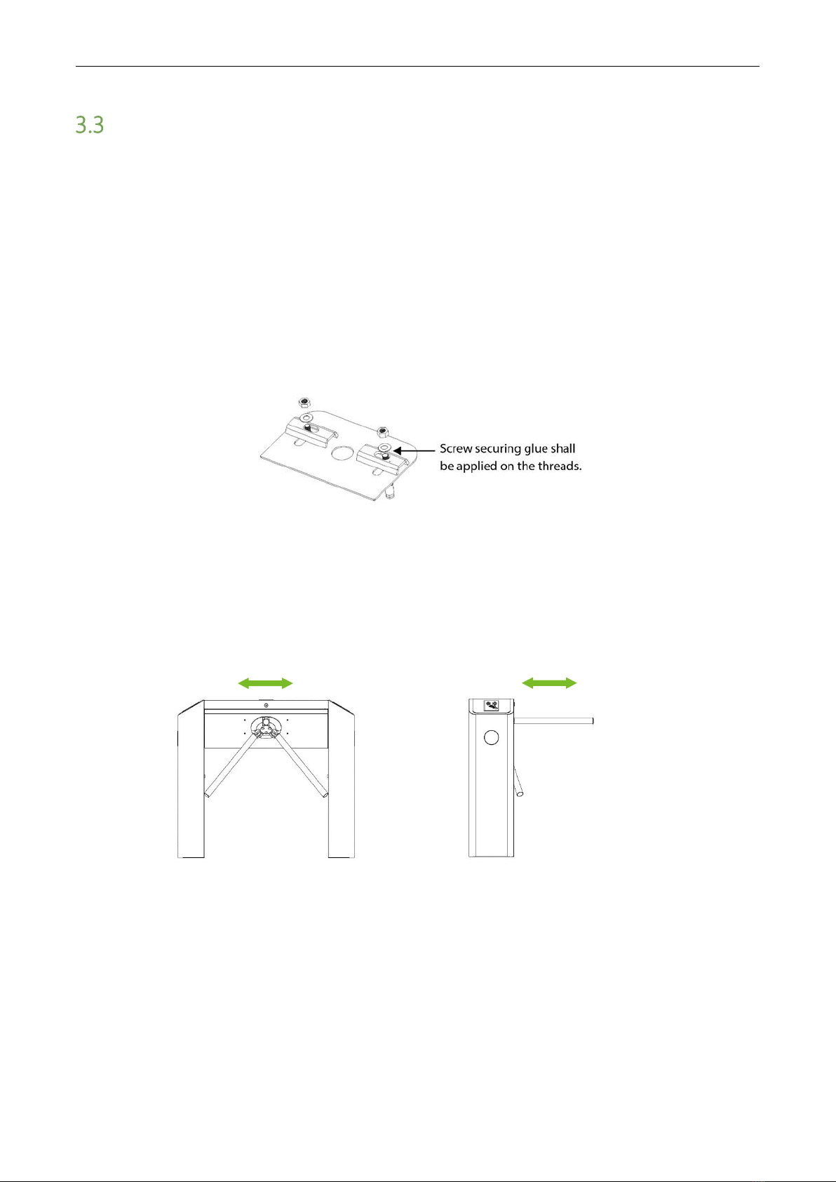
Place the mounting plate properly, then apply screw securing glue on the surface and threads of the
expansion bolts, install four expansion bolts to secure the mounting plate, and use a horizontal ruler
to test the levelness of the mounting plate. If the mounting plate is not levelled, adjust it with the
gaskets provided. Note that all the four expansion bolts must be installed properly, as shown in
Figure 3-4.
Figure 3-4
3. Install the turnstile on the mounting plate and tighten the screws. Apply screw securing glue
before using and putting gaskets on the screws to adjust the direction of the turnstile. If the
tripod turnstile is not levelled, you can place gaskets to adjust, as shown in Figure 3-5.
Installation levelness Installation levelness
Figure 3-5
TS200 Series Tripod Turnstile User Manual
P a g e |9
4Cable Diagram
Function Description of the Turnstile Control Board
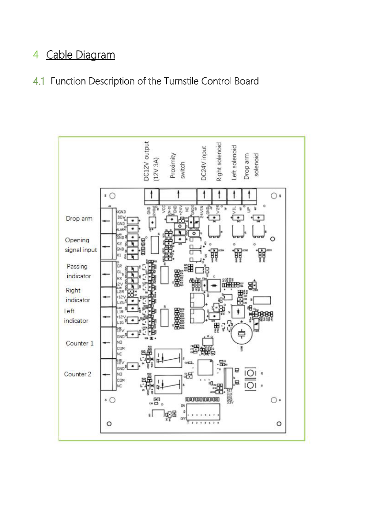
If you are using standard device that without RFID or Fingerprint reader, you need to connect access
control system to the main board, please check the content in this chapter carefully.
Turnstile control board’s diagram as shown in Figure 4-1.
Figure 4-1
Table des matières
Autres manuels ZKTeco Accessoires pour appareils photo


