ZiLOG System 8000 Guide rapide de l'utilisateur

In
affiliate
of
E'K0N
Corporation
System 8000™ Central
PrG~essing
Unil
liardwareBf!~eleDCe
···Manaal
II
•
••
•
-
~
•.
~
•
••
,

03-3200-01
September,
1982
Copyright
1982
by Zilog, Inc. All rights reserved. No part
of
this publication may be
reproduced, stored in aretrieval system,
or
transmitted, in any form
or
by any
means, electronic, mechanical, photocopying, recording, or otherwise, without the
prior written permission
of
Zilog.
The information in this publication
is
subject to change without notice.
Zilog assumes no responsibility for the use
of
any circuitry other than circuitry
embodied in aZilog product. No other circuit patent licenses are implied.

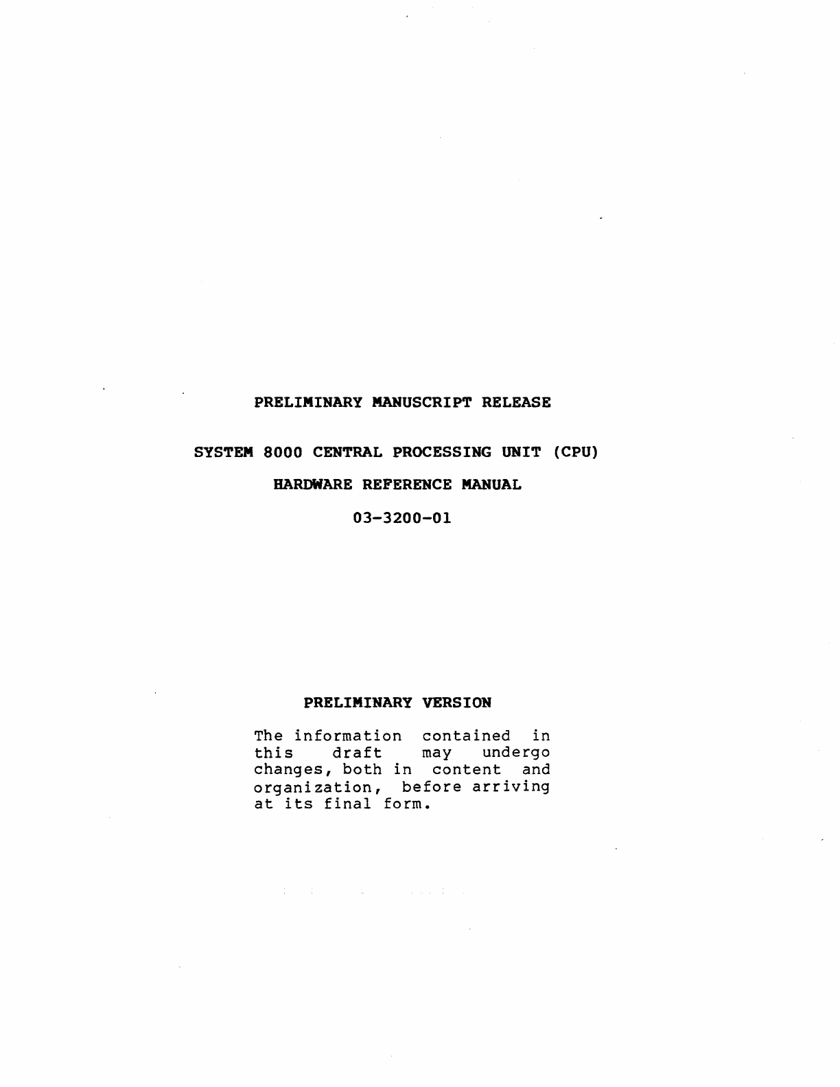
PRELIMINARY
MANUSCRIPT
RELEASE
SYSTEM
8000
CENTRAL
PROCESSING
UNIT (CPU)
HARDWARE
REFERENCE
MANUAL
03-3200-01
PRELIMINARY
VERSION
The
information
contained
in
this
draft
may
undergo
changes,
both
in
content
and
organization,
before
arriving
at
its
final
form.

CPU
i i
Zilog
Zilog
CPU
ii

CPU
Zilog
Preface
CPU
..
The
System
8000
CPU
Hardware
Reference
Manual
descl;ibes
the
processor
board
cap?bilities
and
application
within
the
Sys-
tem
8000.
Logic
Diagrams
are
provided
within
the
Appendix
and
referenced
to
the
circuit
descriptions
in
Section
4.
The
board
is
factory
prepared,
installed
and
tested
in
the
users
system
before
shipment
and
should
require
no
changes.
Any
field
change
should
be
by
qualified
field
service
per-
sonnel.
The
following
listed
manuals
provide
more
technical
documen-
tation
for
the
System
8000:
Title
System
8000
HRM
Zeus
System
Administrator
Manual
Zeus
Utilities
Manual
Zeus
Reference
Manual
Zilog
Number
03-3237
03-3246
03-319f1
03-3195'
iii
Zilog
iii

CPU
iv
Zilog
Zilog
CPU
iv

CPU
Zilog
CPU
Table
of
Contents
SECTION
1
OVERVIEW
...................................
1-1
1.
1.
1.2.
1.3.
Description
•••••••••••••••••••••••••
Serial
and
Parallel
I/O
•••••••••••••
Memory
and
Memory
Management
••••••••••••••••••
1-1
1-2
1-5
SECTION 2SPECIFICATIONS
2-1
2-1
2-1
2-1
2-1
2-2
2-5
2-6
2-6
2-6
2-7
2-7
2-8
........
Definitions
•••••••••••••••••••
Lines
••••••••••••••••••••
•
••
Introduction
•••••••••••••
•
••••••••••••••••
Electrical
Specifications
•••••••••••••••
Physical
Specifications
•••••••••••••••••••••••
Environmental
Specifications
••••••••
CPU
I/O
Connector
•••••••••••••••
2.6.
Bus
Signals
•••••••••••••••••••••••
2.6.1.
ZBI
Signal
2.6.2.
ZBI
Status
2.6.3.
Data
Width
Codes
•••••••••••••••••••••••••
Jumper
Selection
••••••••••••••••••••••••••••••
Line
Printer
Jumper
Selection
••••••••••••••
Baud
Rate
Selection
•••••••••••••••••••••
2.1.
2.2.
2.3.
2.4.
2.5.
2.7.
2.8.
2.9.
SECTION
3
FUNCTIONAL
DESCRIPTION .....................
3-1
·..........
.................
·...............
·...............
3-1
3-1
3-2
3-3
3-3
3-3
3-4
3-4
3-5
3-6
3-8
3-9
3-9
3~9
3-10
3-10
3-11
3-11
3-13
•••
'.'
•••••'••••
•.••
~
•••
-••••
'.'
••
e·.".
.............................
..............................
.......
'.
...........................
3.1.
Description
3.1.1.
Z8001A
CPU
Memory
Addressing
3.1.2.
Z8010A Memory
Management
Units
•••••••••••
3.2.
Memory
Addressing
••••••••
3.2.1.
Local
Memory
••••••••
3.2.2.
SCR
Memory
Selection
•••••••••••••••••••••
3.2.3.
Main
Memory......................
••
3.2.4.
Byte
Transactions
•••••••••••••
3.3.
I/O
Addressing
•••••••••••
3.3.1.
Standard
I/O
3.3.2.
Special
I/O
3.3.3.
Offboard
I/O
••••••••••
3.4.
Reset,
Interrupts
and
Traps
3.4.1.
System
Reset.
3.4.2.
Non-maskable
Interrupts
•••••••••••
3.4.3.
NMI
Identification
•••••••••••••••
3.4.4.
Vectored
Interrupts
••••••••••••••••••••••
3.4.5.
The VI
Daisy
Chain
•••••••
3.4.6.
Non-vectored
Interrupts
v
Zi10g
v

CPU
Zilog
CPU
3• 4•
7.
Tr
a
ps
••••••••••••••••••••••••••••••••••••
3-13
3.5.
Memory
Management
•••••••••••••••••••••••••••••
3-14
3.5.1.
MMU
Configuration
and
Control
••••••••••••
3-15
3.5.2.
System
Configuration
•••••••••••••••••••••
3-17
SECTION 4CIRCUIT DESCRIPTION ........................
4-1
4-1
4-2
4-3
4-3
4-4
4-4
4-5
4-5
4-7
4-7
4-7
4-8
4-9
4-9
4-10
4-11
4-11
4-11
4-12
4-12
4-13
4-13
4-14
4-14
4-14
4-16
4-16
4-17
4-17
4-17
4.1.
Z800JA
CPU
••••••••••••••••••••••••••••••••••••
4.2.
Clock
Generation
••••••••••••••••••••••••••••••
4.2.1.
Baud
Clock
•••••••••••••••••••••••••••••••
4.2.2.
Real
Time
Clock
••••••••••••••••••••••••••
4.3.
Parallel
I/O
Ports
••••••••••••••••••••••••••••
4.3.1.
Printer
Control
Outputs
••••••••••••••••••
4.3.2.
Printer
Status
Inputs
••••••••••••••••••••
4.4.
Serial
Input/
Output
••••••••••••••••••••••••••
4.4.1.
SIC/CPU
Interface
••••••••••••••••••••••••
4 •
5.
In
te
r r
upts
••••••••••••••••••••••••••••••••••••
4.5.1.
Vectored
Interrupt
•••••••••••••••••••••••
4.5.2.
vectored
Interrupt
Daisy
Chain
•••••••••••
4.5.3.
NMI
Identification
•••••••••••••••••••••••
4.5.4.
System
Reset
Logic
•••••••••••••••••••••••
4.6.
Memory
Addressing
•••••••••••••••••••••••••••••
4.6.1.
Byte
Transactions
••••••••••••••••••••••••
4.6.2.
Read-Only
Memory
•••••••••••••••••••••••••
4.6.3.
Read/Write
Memory
••••••••••••••••••••••••
4.7.
Byte
Swap
Buffer
••••••••••••••••••••••••••••••
4.8.
Memory
Management
Control
Logic
•••••••••••••••
4.8.1.
Non-segmented
Operating
System
•••••••••••
4.8.2.
Non-segmented
User
Program
•••••••••••••••
4.8.3.
Segmented
User
Program
•••••••••••••••••••
4.8.4.
MMU
Configuration
••••••••••••••••••••••••
4.9.
System
Configuration
Register
•••••••••••••••••
4.9.1.
SCR
Configuration
••••••••••••••••••••••••
4.9.2.
segmented/Non-segmented
User
•••••••••••••
4.9.3.
parity
Error
Checking
••••••••••••••••••••
4.10.
Special
Logic
Circuits
•••••••••••••••••••••••
4.10.1.
External
Violation
Registers
••••••••••••
4.10.2.
Address/Data
Buffers
and
Steering
Logic
••••••••••••••••••••••••••••••••••
4-17
4.10.3.
T2,
T3
Wait
State
Generator
Logic
•••••••
4-18
4.10.4.
peripheral
Handshaking
Logic
••••••••••••
4-19
4.10.5.
Segment
Trap
Logic
and
Suppress
•••••••••
4-20
vi
Zilog
vi

CPU
Zilog
CPU
SECTION
5
MAINTENANCE
•••••••••••••••••••••••••••••••
e.
5-1
5.1.
General...............
•
•••••
5.2.
Preventive
Maintenance
••••••
5.3.
Corrective
Maintenance
••••••••••
5.3.1.
System
Power-up
Di
agnost
ics
•••••••••.••
5.3.2.
Inspection
and
Replacement
••••••••••••
5-1
5-1
5-1
5-1
5-6
SECTION 6
TIMING
.....................................
6-1
6-1
6-1
6-3
6-4
6-5
6-6
6-6
6-7
................
General
••••••••••••••
Memory Read
and
Write
Input/Output
Timing
6.4.
Interrupt
Operation
•••••••••
•
•••••••••••••
6.4.1.
Status
Saving
Sequence
•••
•
•••••••••••••
6.4.2.
Bus
Request
Ackn~wledge
Timing
•••••••••
6.5.
peripheral
Interrupt
Timing
•••••••••••••••••
6.5.1.
Return
from
Interrupt
••••••••••••••••••
6.1.
6.2.
6.3.
APPENDIX
A
16
KILOBYTE
EPROM
MEMORY
..................
A-I
APPEllDIX BLOGIC
DIAGRAMS
B-1
vii
Zilog
vii

CPU
Zi10g
List
of
Illustrations
CPU
Figure
1-1
1-2
System
8000
CPU
Board
•••••••••••••••••••••••
1-3
CPU
Functional
Diagram
••••••••••••••••••••••
1-4
2-1
9~
pin
Euro
Standard
Connector
••••••••••••••
2-2
3-1
Peripheral
Interrupt
priority
•••••••••••••••
3-13
4-1
4-2
4-3
4-4
4-5
4-6
4-7
4-8
4-9
4-10
4-11
6-1
6-2
6-3
6-4
6-5
6-6
6-7
vi
ii
Clock
Generation
Circuit
••••••••••••••••••••
Baud
Clock
Generator
•••••••••••••••••••••
~
••
Parallel
I/O
••••••••••••••••••••••••••••••••
Serial
I/O
with
CTC
Channels
••••••••••••••••
vectored
Interrupt
••••••••••••••••••••••••••
Interrupt
priority
Connection
•••••••••••••••
System
Reset
Logic
••••••••••••••••.•••••••••
System
Configuration
Register
•••••••••••••••
Setting
Console
Baud
Rate
(9600
Baud)
for
a-inch
Disk
•••••••••••••••••
T3
Wait
State
Generator
Logic
•••••••••••••••
Peripheral
Handshaking
Logic
••••••••••••••••
Memory Read and
Write
Timing
••••••••••••••••
Write
Cycle
•••••••••••••••••••••••••••••••••
Read
'Cycle
•••••••••••
:
••••••••••••••••••••••
Segment
Trap/Interrupt
Acknowledge
Cycle
••••
Bus
Request
Acknowledge
Cycle
•••••••••••••••
Interrupt
Acknowledge
Cycle
•••••••••••••
0
•••
Return
from
Interrupt
Cycle
•••••••••••••••••
Zilog
4-3
4-3
4-4
4-6
4-8
4-9
4-10
4-15
4-16
4-19
4-20
6-2
6-4
6-4
6-5
6-6
6-7
6-8
viii
Autres manuels pour System 8000
2
Table des matières
Autres manuels ZiLOG Ordinateur de bureau