Zero Z02 Series Guide rapide

zero
HOME AUTOMATION
Z02 - SWING GATE
PG1
USER MANUAL AND CONFIGURATION
Z02.REV01.2018
IT | EN | FR
zero
HOME AUTOMATION Z02 - SWING GATE MOTOR
SUPPLY 230-24V

zero
HOME AUTOMATION Z02 - SWING GATE
PG2
zero
HOME AUTOMATION

zero
HOME AUTOMATION
Z02 - SWING GATE
PG3
INDEX
01. SAFETY INSTRUCTIONS
02. OPERATOR
TECHNICAL SPECIFICATIONS
DIMENSIONS
03. INSTALLATION
INSTALLATION DIMENSIONS
INSTALLATION STEPS
TYPICAL INSTALLATION
04. MAINTENANCE
MANUEL RELEASE
05. TROUBLESHOOTING
01. SAFETY INSTRUCTIONS
ATTENTION:
•To ensure the safety of people, it is important that you read all the following instrucons.
Incorrect installaon or incorrect use of the product can cause physical injury and material
damage.
•Keep these instrucons in a safe place for future reference.
•This product was designed and produced strictly for the use indicated in this manual. Any
other use, not expressly indicated here, could compromise the good condion/ operaon of
the product and/or be a source of danger.
•ZERO SRLS. is not responsible for the improper use of the product, or other use than that
for which it was designed.
•ZERO SRLS. is not responsible if safety standards were not taken into account when instal-
ling the equipment, or for any deformaon that may occur to it.
•ZERO SRLS. is not responsible for the safety and proper operaon when using components
not sold by them.
•Do not make any modicaons to the operator components and / or their accessories.
•Before installaon unplug the automasm from the source of power.
•The installer must inform the client how to handle the product in case of emergency and
provide this manual to user.
•Keep remote controls away from children, to prevent the automated system from being
acvated involuntarily.
•The customer shall not, under any circumstances, aempt to repair or tune the operator
.Must call qualied technician only.
•Connect the automasm to a 230V plug with ground wire.
•Operator for outdoor and indoor use.

zero
HOME AUTOMATION Z02 - SWING GATE
PG4
02. OPERATOR
TECHNICAL SPECIFIATIONS
Z02 specicaons are as follow:
962mm || 1162mm || 1562mm
175mm
159mm
647mm || 747mm || 947mm 104mm
DIMENSIONS
Z02 300 || 400 || 600 dimensions are the following:
Z02.400 Z02.400.24 Z02.600 Z02.600.24
Power Supply 230Vac 50/60Hz 24Vdc 230Vac 50/60Hz 24Vdc
Power 180W 60W 180W 60W
Current 1,4 A 1- 3 A 1,4 A 1-3 A
Capacitor 8µF - 8µF -
RPM 1400
Noise level LpA <= 50 dB (A)
Force 2300 N
Operang temperatures -25°C to 65°C
Thermal protecon 120°C - 120°C -
Protecon class IP54
Working frequence 25% INTENSIVE 25% INTENSIVE
Opening me 13-18 seconds 20-28 seconds

zero
HOME AUTOMATION
Z02 - SWING GATE
PG5
03. INSTALLATION
INSTALLATION DIMENSIONS
Z02 specicaons are as follow: The operator Z02 must be installed with a small inclinaon , to
prevent water inltraon through the extension arm.
For this, the front support must be xed to the gate with a height lower than the height of the
rear support. See example below:
Dimension A • Vercal distance from the oor to the top of the rear support .
Dimension B • Vercal distance from the oor to the top of the front support.
Example:
• Set dimension A (this can be any size of your choice).
• Aer you set dimension A, subtract 10mm to nd dimension B.
• If the height of the rear bracket (dimension A)is set at 600 mm, then the height of the front
bracket (dimension B) will be 590 mm (600mm-10mm).
It is very important that these dimensions are respected! Only this way can be
as- sured the correct funconing and durability of the operators!
It is also very important to have a levelled ground/terrain!

zero
HOME AUTOMATION Z02 - SWING GATE
PG6
(EXTERIOR)
Axis of rotation of the
motor, on the front bracket
Axis of rotation of the gate Closingm echanical
(centero ft he door hinge) stopper
Y
W
Distance between the
centers of the holes on th e
X
supports from operator
Axis of rotation of the
motor,on ther ears upport Opening
direction
(INTERIOR)
Opening mechanic al stopper
On the Illustrated diagrams below and are the dimensions for the installaon of the automated
system.
Opening mechanic al stopper
Opening
direction
(EXTERIOR)
Axis of rotation of theg ate
(centero ft he door hinge)
Y
W
Closingm echanical
stopper
X
Axis of rotation of the motor
(INTERIOR)
on thef ront support
Axis of rotation of theD istance between the centers of the
motor,on ther ears upport holeso nt he supports from operator
X Y W
Z02.400 95° 160-200 120-180 695-700
Z02.600 95° 160-300 120-280 900-905
OPENING ANGLE

zero
HOME AUTOMATION
Z02 - SWING GATE
PG7
It is very important that these dimensions are respected! Only this way can be
assured the correct funconing and durability of the operators!
Legend:
Dimension X - Horizontal distance between hinge axis of the door and the rear axle of
the motor.
Dimension Y- Vercal distance between hinge axis of the door and the rear axle of the
motor.
Dimension W - Distance between axis of the motor brackets
01 • Fixing rear support
• The Rear support must be xed to the
pillar or wall using dimensions provided in
the preceding pages.
It can be xed using screws with mechani-
cal bushing or chemical welding process,
or one of your choice since it provides an
appropriate support.
02 • Fixing front support
• The Front support should be xed to the
gate, respecng height dimensions and di-
stance to the rear support.
This may be xed by using screws, welding
process, or to choose another long as it
provides a secure proper support.
INSTALLATION STEPS
X Y W
Z02.400 95° 120-180 120-180 1095-1100
120° 160-180 120-140 1095-1100
Z02.600 95° 120-350 120-200 1495-1500
120° 200-280 120-200 1495-1500
OPENING ANGLE

zero
HOME AUTOMATION Z02 - SWING GATE
PG8
03 • Remove caps and pins from motor
• Before installing motor, remove caps and
pins from motor.
• At the end of the installaon, put back
plasc covers for a beer visual nish of
the operator.
04 • Install operator on the supports
• The operator must be placed on both
supports the same me to avoid
leaving the operator suspended by only
one of the supports.
To make the task easier, you should unlock
the operator in order to be able to stretch
/ retract arm easily,to get the correct posi-
on for supports.
05 • Test movement
• Install the pins removed earlier on each
place with a small amount of lubricant for
less fricon.
•Move the door manually to see if the
door opens and closes uniformly and cor-
rectly, without any irregular fricon during
its enre travel;
This will ensure that operator is not
subjected to problems during operaon.
06 • Connecng operator to control board
and conguring control devices.
•With the operator installed, connect it to
control board for system conguraon (see
control board user manual).
Must also congure the desired control
devices (transmiers, wall switch, etc.) and
other addional components such as an-
tenna, warning light, key selector, among
others.
It is important to respect this installaon order!
Otherwise, it is not possible to ensure correct installaon and operators may not
work properly!
zero
HOME AUTOMATION
Z02 - SWING GATE
PG9
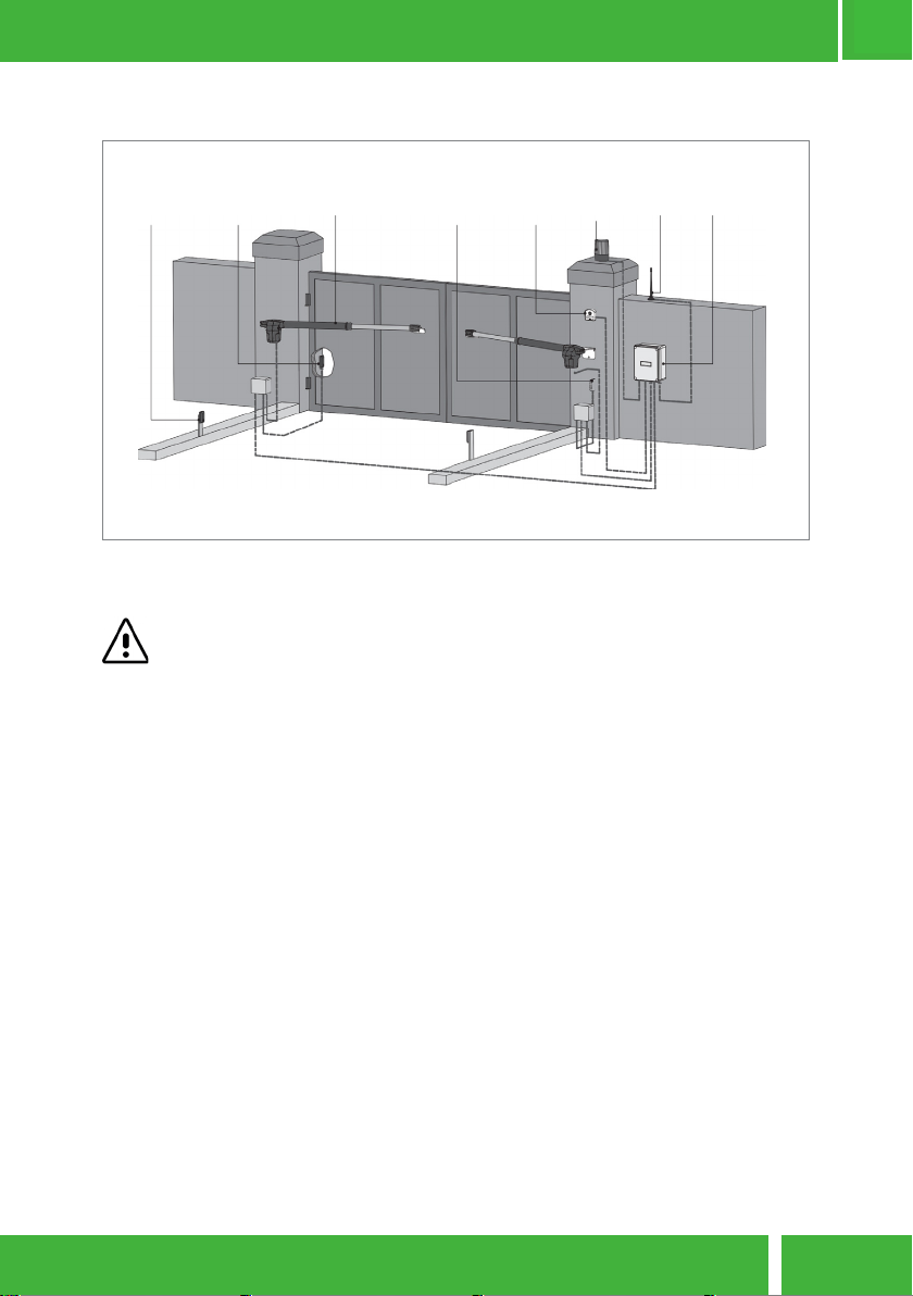
•
INTERIOR
PHOTOCELLS
•
EXTERIOR
PHOTOCELLS
•
MOTOR
•
EXTERIOR
PHOTOCELLS
•
KEY
SELECTOR
•
WARNING
LAMP
•
ANTENNA
• CONTROL
BOARD
TIPICAL INSTALLATION
It is important to use mechanical stoppers in the opening and closing posion of
the gate. If not respected, components of the automaon may suer eorts for
which they were not prepared, and as a result will be damaged.
It is important to use juncon boxes for connecons between motors, components
and control unit. All cables must enter and exit on the boom of the juncon and
control board box.
zero
HOME AUTOMATION Z02 - SWING GATE
PG10
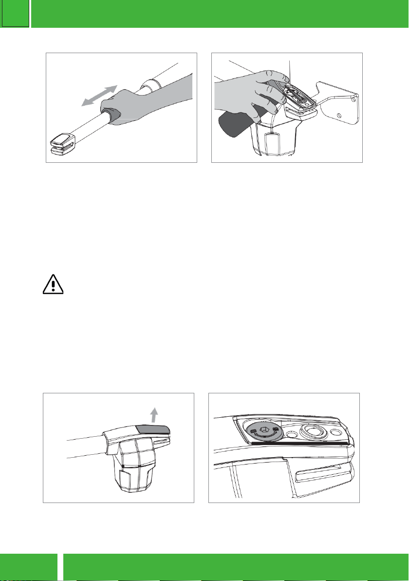
01 • Remove the plasc cap from the rear
end
Informaon engraved on the unlock sha
D=Unlock || B=Lock
• Clean stainless steel arm
• With a cloth soaked in lubricant spray,
wipe any residue that accumulates on the
operator’s stainless steel arm.
• Apply a small amount of spray lubricant
on the arm and using a dry cloth remove
the excess, leaving a homogeneous layer of
lubricant over the arm.
• Lubricate pins
• Remove front and rear caps
• Place a small amount of lubricant on the
holes that contains support pins.
• Install caps on the respecve holders.
04. MAINTENANCE
Check motor supports: Make sure that supports remain well xed on the pillars and
gate to ensure proper funconing of the equipment.
These maintenance measures must be applied every year in order to insure proper
funconing of the automated system.
MANUAL RELEASE
To open manually the gate in case of electric power failure or in case of damage, follow the
below steps:
Ce manuel convient aux modèles suivants
4
Table des matières
Autres manuels Zero ouvre-porte de garage


Manuels ouvre-porte de garage populaires d'autres marques


Craftsman
Craftsman 139.53924 Manuel utilisateur

Chamberlain
Chamberlain MyQ 940ESTD Manuel utilisateur

Automatic Technology
Automatic Technology GDO-9V1 SecuraLift Manuel utilisateur

Westfalia
Westfalia 19 36 07 Manuel utilisateur

Chamberlain
Chamberlain HD520EVP Manuel utilisateur

Cardin
Cardin BL Series Manuel utilisateur