Zander Aachen MINOS SD1E Manuel utilisateur
Operating Instructions
Safety Relay MINOS SD1E
MINOS SD1E

2
Safety Relay MINOS SD1E
H. Zander GmbH & Co. KG
Am Gut Wolf 15
52070 Aachen, Germany
www.zander-aachen.de
Version: K11 E61-347-00
Engl. Translation of the original document
Subject to technical modifications,
no responsibility is accepted for the
accuracy of this information.

3
Safety Relay MINOS SD1E EN
Contents
1. Scope..................................................................................................................... 4
2. Target group .......................................................................................................... 4
3. Safety instructions.................................................................................................. 4
4. Appropriate use...................................................................................................... 5
5. Disclaimer and warranty......................................................................................... 6
6. Features................................................................................................................. 7
7. Function ................................................................................................................. 7
8. Application examples ............................................................................................. 9
9. Mounting .............................................................................................................. 12
10. Electrical connection ........................................................................................... 12
11. Commissioning ................................................................................................... 13
12. Checks and maintenance.................................................................................... 14
13. Proof-Test ........................................................................................................... 15
14. Terminal assignment and LED displays............................................................. 16
15. Wiring / Applications............................................................................................ 17
16. Time diagrams ................................................................................................... 24
17. Monitoring table .................................................................................................. 26
18. Dimensions ......................................................................................................... 28
19. Safety parameters............................................................................................... 28
20. Technical data..................................................................................................... 30
21. Derating .............................................................................................................. 33
22. Variants / Ordering-No. ....................................................................................... 34
23. Service................................................................................................................ 35
24. Declaration of conformity .................................................................................... 36
25. Edition of listed standards................................................................................... 38

4
Safety Relay MINOS SD1E
• who are familiar with proper handling of the
safety components
• who are familiar with the applicable EMC
and ESD regulations
• who are familiar with the local regulations
concerning work safety and accident
prevention
• who have read and understood these
operating instructions.
The user shall be responsible for integrating
the device into a safe overall system. For this
purpose, the overall system has to be vali-
dated, e.g. according to EN ISO 13849-2.
Opening the device, any kind of manipulation
to it and bypassing the safety devices are not
permitted.
The device version (see nameplate "Ver.")
should be stored and checked before every
commissioning. If there is a version change,
the use of the device in the overall application
should be revalidated.
1. Scope
This document is valid for the following safety
modules:
MINOS SD1E (Order-No.: 472841)
2. Target group
Specialist electricians and assembly, setup
and service specialists who possess special
knowledge in working with safety compo-
nents.
3. Safety instructions
Safety components are intended to
protect people. Not following the
safety instructions, improper instal-
lation or manipulation may result in
fatal injuries to persons and damage to
property. Safety devices must not be by-
passed, removed or manipulated in any way.
Please follow all the safety instructions and
warnings mentioned in this document.
Installation, commissioning, maintenance,
and decommissioning should be done only by
authorised and qualified technicians:

5
Safety Relay MINOS SD1E EN
4. Appropriate use
MINOS SD1E is a safety emergency stop
relay for monitoring e.g. emergency stop
buttons, safety doors and light curtains. The
modules are also certified for operation in
furnaces and vessels according to
EN 50156-1 / EN 746-2.
The approved operating parameters for use
must be complied (see chapter 20 "Technical
data").
A risk assessment should be carried out on
the machine before using the device. For
example, according to:
EN ISO 13849-1, Safety-related parts of
control systems, Appendix A
EN ISO 12100, Safety of machinery - General
principals for design - Risk assessment and
risk reduction
IEC 62061, Safety of machinery - Functional
safety of safety-related electrical, electronic
and programmable electronic control sys-
tems.
Additional requirements may have to be
considered depending on the type of machine
or plant.
Appropriate use also includes compliance
with:
EN ISO 13849-1, Safety-related parts of
controllers,
EN 60204-1, Electrical equipment in
machines.
For further information please
refer to the above mentioned
documents.
ATTENTION!
• The user is responsible for integrating the
device into a safe overall system. For this
purpose, the overall system has to be
validated, e.g. according to
EN ISO 13849-2
• If a operating instruction is enclosed with
the product, then the specifications given in
the operating instruction are applicable

6
Safety Relay MINOS SD1E
5. Disclaimer and warranty
If the above mentioned conditions for appro-
priate use are not complied with or if the
safety instructions are not followed or if any
maintenance operations are not carried out as
required, this shall lead to an exclusion of
liability and loss of warranty.
ATTENTION!
We would like to point out that it is the full
responsibility of the operator to ensure a plant
availability.
Using the SD1E, a safety emergency stop
relay according to
• EN ISO 13849-1
• IEC 62061
• IEC 61508
• EN 50156-1
• EN 746-2
• IEC 61511-1
is used, which will be brought into the safe
state when the safety function is requested.
This means that the connected load is
switched off as soon as a request from con-
nected sensor elements or diagnostic meas-
ures detects a dangerous state, e.g. caused
by a component fault.
Since process-related applications in particu-
lar have high demands on availability, limited
availability can also have significant conse-
quences.
It is therefore recommended to stock a sec-
ond unit to avoid long downtimes in such a
case.
These are recommendations of the manufac-
turer, the evaluation of the importance of the
plant availability is the sole responsibility of
the operator.

7
Safety Relay MINOS SD1E EN
6. Features
• Use up to PL e, Cat. 4, SILCL 3
• Certified for operation in
furnaces and vessels according to
EN 50156-1 / EN 746-2.
• Stop Category 0 according to EN 60204-1
• 1 two-channel safe input
• 1 safe relay contact
• 1 auxiliary output (PNP)
• Automatic or monitored manual start
selectable at the device
• 6.8 mm width
• Extensive monitoring via front LED‘s
7. Function
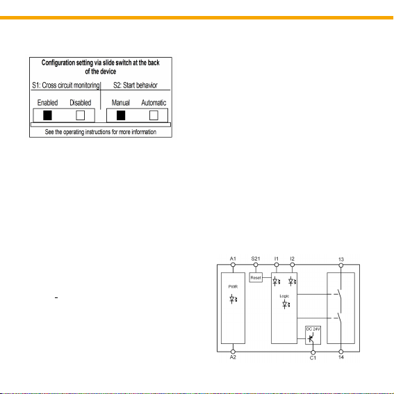
Config-Switches S1 and S2:
At the back of the device are two slide-
switches (S1 and S2) to configure the SD1E.
The following functions can be configured:
With the Config-Switch S1, the function of the
safety circuit at I1 / I2 can be configured.
According to your application a cross circuit
monitoring can be enabled or disabled (see
Fig. 1)
With the Config-Switch S2, the function of the
start input at S21 can be configured. An
automatic start or an monitored, manual start
can be set.
For this, turn the SD1E until the printed
configurationtable (see Fig. 1) is facing up
and the opening at the back of the device is
visible. Two slide switches can be seen,
which you can slide to the left or right side
depending on the desired configuration (see
Fig. 1).
8
Safety Relay MINOS SD1E
For example:
For a two channel application with cross
circuit monitoring and automatic start the
Config-Switches must be set as follows:
Config-Switch S1: Left (Enabled)
Config-Switch S2: Right (Automatic)
Safety circuit I1 / I2:
The safety circuit is designed to be used as
single or dual channel via I1 and I2 depending
on the wiring and the position of the Config-
Switch S1 (see chapter 12 “Commissioning”).
Start input S21:
A monitored, manual start or an automatic
start is provided via the terminal S21. The
start function can be set via the Config-Switch
S2 on the back of the device. (see chapter 12;
“Commissioning”).
Safe relay contact 13-14:
Considering the start behaviour, the safe
relay contact switches on at the time the
safety circuit closes. Opening the safety
circuit results in an immediate shutdown (safe
condition).
Auxiliary output C1:
The PNP-semiconductor output switches
invertedly to the safe relay contact and may
not be used as safe output.
Behaviour in case of a fault:
It is ensured that one single fault does not
lead to loss of the safety function and that
every fault is detected latest when the system
Fig. 2 Block diagram SD1E
Fig. 1 Configurationtable SD1E

9
Safety Relay MINOS SD1E EN
Note: Config-Switches are set as follows:
S1: Enabled / S2: Manual
(see chapter 7. “Function”)
8. Application examples
Application example 1:
SD1E for two-channel emergency-stop
monitoring with short circuit monitoring and
monitored manual start up to PL e / SIL 3.
Fig. 3 Two-channel emergenc -stop monitoring
with cross circuit monitoring
Application example 2:
SD1E for single-channel emergency stop
monitoring with automatic start up to
PL c / SIL 1.
Fig. 4 Single-channel emergenc stop
monitoring with auto-start
Note: Config-Switches are set as follows:
S1: Disabled / S2: Automatic
(see chapter 7. “Function”)

10
Safety Relay MINOS SD1E
Application example 4:
SD1E for dual channel safety door monitoring
with manual start up to PL e / SIL 3.
Fig. 6 Dual channel safet door monitoring
Note: Config-Switches are set as follows:
S1: Enabled / S2: Manual
(see chapter 7. “Function”)
Note: Config-Switches are set as follows:
S1: Enabled / S2: Automatic
(see chapter 7. “Function”)
Application example 3:
SD1E for two-channel monitoring of a non-
contact safety switch with short circuit moni-
toring and automatic start up to PL e / SIL 3.
Fig. 5 Dual channel safet door monitoring
with non-contact safet switch
Table des matières
Autres manuels Zander Aachen Relais

Zander Aachen
Zander Aachen SR3C Manuel utilisateur

Zander Aachen
Zander Aachen SR3E Manuel utilisateur

Zander Aachen
Zander Aachen ZX09 Series Manuel utilisateur

Zander Aachen
Zander Aachen SR7D Manuel utilisateur

Zander Aachen
Zander Aachen SR4C Manuel utilisateur

Zander Aachen
Zander Aachen SR3D Manuel d'utilisation

Zander Aachen
Zander Aachen SR3C Manuel d'utilisation

Zander Aachen
Zander Aachen MVisio HMI Pro Manuel utilisateur

Zander Aachen
Zander Aachen SR2C Manuel utilisateur

Zander Aachen
Zander Aachen SR7C Manuel d'utilisation


