ZAHNER PAD4 Manuel utilisateur

( )
20/12/2022

PAD4
Caution!!!
Please read the risk assessment document before operating the potentiostat.
Prevent the inputs of the potentiostat from electrostatic discharge (ESD)! ESD may
damage the potentiostat. ESD-related damages are not covered by the warranty of
the potentiostat. The user must make sure to discharge his-/herself from any
electrical charge before touching the potentiostat (TIP: use grounded ESD-matts).
Maintain the maximum input voltage of the device and the selected voltage range.
Use electrically insulated thermocouples.
Do not expose the PAD4 card to heat.

PAD4
1 Introduction ............................................................................................... 3
1.1 Packing List...........................................................................................5
2 PAD4: Technical Data............................................................................... 6
2.1 PAD4-HC Specifications .................................................................... 6
2.2 PAD4-LC Specifications .................................................................... 6
2.3 PAD4-HZ Specifications .....................................................................7
2.4 PAD4 Input Jack Pinout ......................................................................7
2.4.1 2-Pole LEMO Jack (effective until July 2015).............................7
2.4.2 7-Pole LEMOSA Jack (effective from August 2015) .................8
3 Configuration ............................................................................................ 9
3.1 Select PAD4 Channel for AC Voltage Display..................................10
3.2 Select PAD4 Channels for EIS Measurement ..................................10
3.3 PAD4 Calibration............................................................................... 11
3.4 Setup Customized Input Ranges...................................................... 11
3.5 Setup PAD4 Mode............................................................................. 11
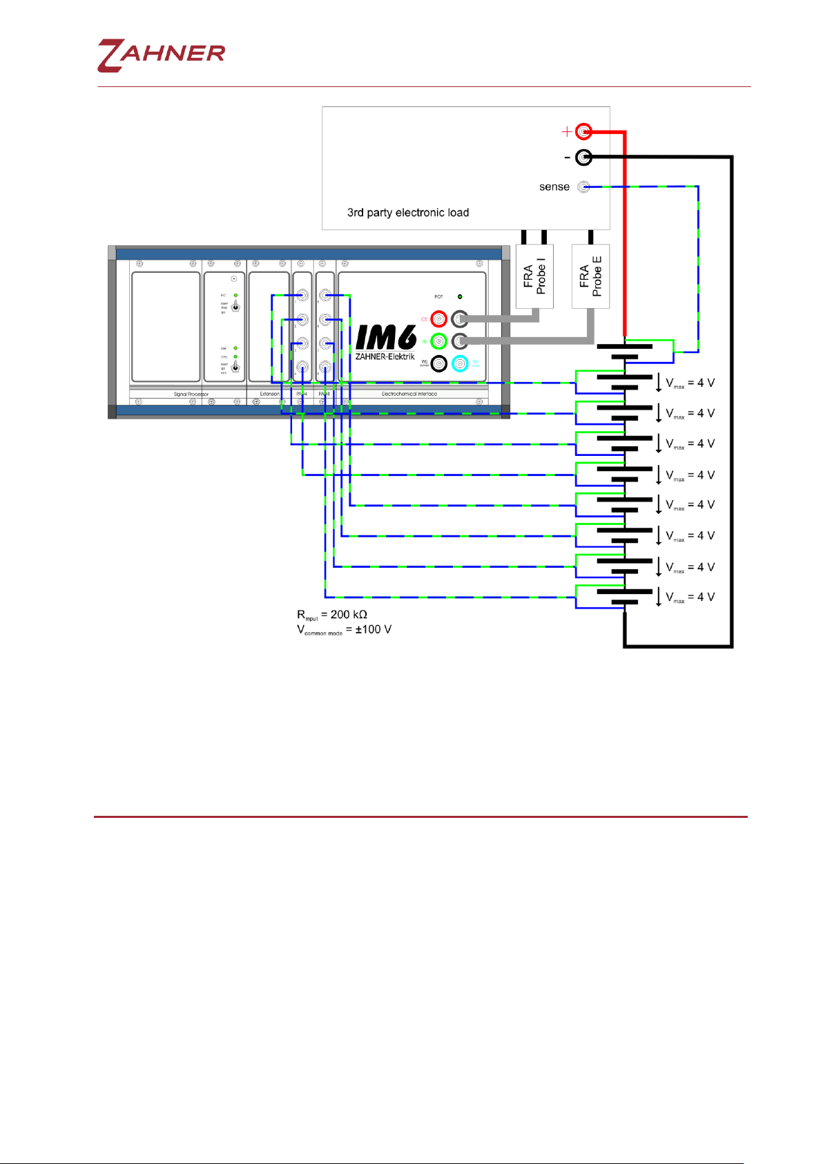
4 Parallel Impedance Measurements ........................................................12
5 Parallel Impedance Analysis....................................................................14
6 DC Measurements and Signal Acquisition .............................................15
6.1 Create ACQ Channels for PAD4........................................................15

PAD4 -3-
1Introduction
The PAD4 was designed for the investigation of stacked objects like batteries and
fuel cells, where the impedance, defined by one common current through the
object, but several voltages accessible on several taps must be acquired in parallel.
Compared to the usual solution with multiplexers like the PMUX series, the PAD4
has the advantage of real parallel acquisition, saving measurement time and
avoiding time lags between the acquisitions of different channels.
PAD4 is a plug-and-play card for an extension slot of the Zennium Pro/X. It allows
connecting four different potential sense inputs for parallel impedance
measurements.
With four PAD4 add-on cards up to 16 channels synchronous measurements can
be done in parallel to the main channel.
The Zennium Pro can control one PAD4 add-on card with 4 additional parallel
sense channels. The Zennium X can control up to four PAD4 add-on cards with up
to 16 additional parallel sense channels.
Connection scheme for 4 channel PAD4 with a 5 cell battery stack. The maximum
input voltage of each PAD4 channel is limited to ±4 V with a compliance voltage
range of ±100V. The output voltage and current is limited by the electrochemical
workstation. For example the Zennium has a compliance voltage of ±14 V.

PAD4 -4-
Connection scheme for 8 channel PAD4 with an external power potentiostat PP211
(20 V / 10 A) connected via EPC42 to an IM6.

PAD4 -5-
The PAD4 AD converter card is also compatible with a 3rd party electronic load
interfaced from the IM6/Zennium by means of the FRA-Probe.
1.1 Packing List
PAD4 addon card
4 sense cables (Lemosa plug to blue & green twisted cables)
This manual

PAD4 -6-
2PAD4: Technical Data
2.1 PAD4-HC Specifications
Socket:
4x Lemosa EGA.0B.307.CLL
Input Impedance:
100 KΩ
Input Range:
±4 V (standard configuration)
±5 V, ±10 V, ±12 V, ±20 V or ±24 V on demand
Offset Voltage:
±1.0 mV ±0.1% full scale
Common Mode Range:
±100 V
Frequency Range:
10 µHz - 250 KHz
Resolution:
18 bit
Input AC Voltage Resolution
500 nV @ 4 mV AC amplitude
Maximum PAD4 Supported
1 (ZENNIUM PRO)
4 (ZENNIUM X)
2.2 PAD4-LC Specifications
Socket:
4x Lemosa EGA.0B.307.CLL
Input Impedance:
50 KΩ
Input Range:
±1 V
Offset Voltage:
±0.25 mV ±0.1% full scale
Common Mode Range:
±25 V
Frequency Range:
10 µHz - 250 KHz
Resolution:
18 bit
Input AC Voltage Resolution
125 nV @ 4 mV AC amplitude
Maximum PAD4 Supported
1 (ZENNIUM PRO)
4 (ZENNIUM X)

PAD4 -7-
2.3 PAD4-HZ Specifications
Socket:
4x Lemosa EGA.0B.307.CLL
Input Impedance:
>100 GΩ
Input Range:
2x ±5 V
2x ±1 V
Offset Voltage:
±1.0 mV ±0.1% full scale
Common Mode Range:
2x ±10 V (±5 V range inputs)
2x ±2 V (±1 V range inputs)
Frequency Range:
10 µHz - 250 KHz
Resolution:
18 bit
Input AC Voltage Resolution
2x 625 nV @ 4 mV AC amplitude
1x 125 nV @ 4 mV AC amplitude
Maximum PAD4 Supported
1 (ZENNIUM PRO)
4 (ZENNIUM X)
2.4 PAD4 Input Jack Pinout
2.4.1 2-Pole LEMO Jack (effective until July 2015)
1: upper connector female: + green
(reference electrode)
2: lower connector male: - blue
(working electrode sense)
corresponding connector:
LEMO push-pull connector
FFA.0S.302.CLAC32

PAD4 -8-
2.4.2 7-Pole LEMOSA Jack (effective from August 2015)
1: + green (reference electrode)
2: not connected
3: -5 V supply
4: +5 V supply
5: not connected
6: - blue (working electrode sense)
7: GND supply
!
Note: ±5 V supply (pin 3,4,7) only required by
CIMPS-MDTR photosense preamplifier.
corresponding connector:
LEMO push-pull connector
FGA.0B.307.CLAD56

PAD4 -9-
3Configuration
Click on the Z icon at the upper left edge
of the Thales software window and
switch to Control Potentiostat page.
Click on Check Cell Connections.
The Thales software detects the PAD4
cards automatically and shows the
button Parallel Impedance Setup. Click
on that button to switch to Synchronous
Parallel Measurements page.
Ce manuel convient aux modèles suivants
3
Table des matières
Autres manuels ZAHNER Instrument de mesure
Manuels Instrument de mesure populaires d'autres marques

Endress+Hauser
Endress+Hauser Proline Promag 50 Caractéristiques techniques

Siemens
Siemens SITRANS F Coriolis FCT030 Manuel de la liste des pièces

KLINGER
KLINGER CMF V Series Manuel utilisateur

EXFO
EXFO FTB-2 Manuel d'exploitation et d'entretien

Keysight
Keysight M8290A Manuel utilisateur

ADTEK
ADTEK MW-5 Manuel utilisateur


