YOSensi LNRM Manuel utilisateur

YO Modbus
User guide v2.1

YO Modbus User guide v2.1
page 2/33
Release notes
Released
Version
Key changes
25.08.2022
1.0
Initial release.
27.07.2023
2.0
Configuration node description using Yosensi platform
added. Description of MODBUS communication protocol
Device parameters names and description modified.
Configuration file modified. Changed description of
connecting nodes with Yosensi Management Platform.
26.10.2023
2.1
Added configuration with Yosensi Mobile App, updated
documentation.
www.yosensi.io

YO Modbus User guide v2.1
page 3/33
Content
Release notes 2
Content 3
Product description 4
Overview 4
Physical interfaces 5
LEDs 5
Buttons 5
RS485 interface 6
Specifications 7
Physical 7
Operating conditions 8
Measured values 8
Queries and polls 9
Installation 10
Package contents 10
Safety precautions 10
Installation guide 11
Operation 13
IoT system components 13
Device configuration 14
Configurable parameters 14
Parameters description 18
Configuration node via Yosensi Management platform 21
Configuration node with Yosensi mobile app 26
Connecting node with network 27
Yosensi Management Platform configuration 27
Adding node manually 27
Adding node via Bluetooth 29
Payload description 30
Compliance statements 32
www.yosensi.io
YO Modbus User guide v2.1
page 4/33
Product description
Overview
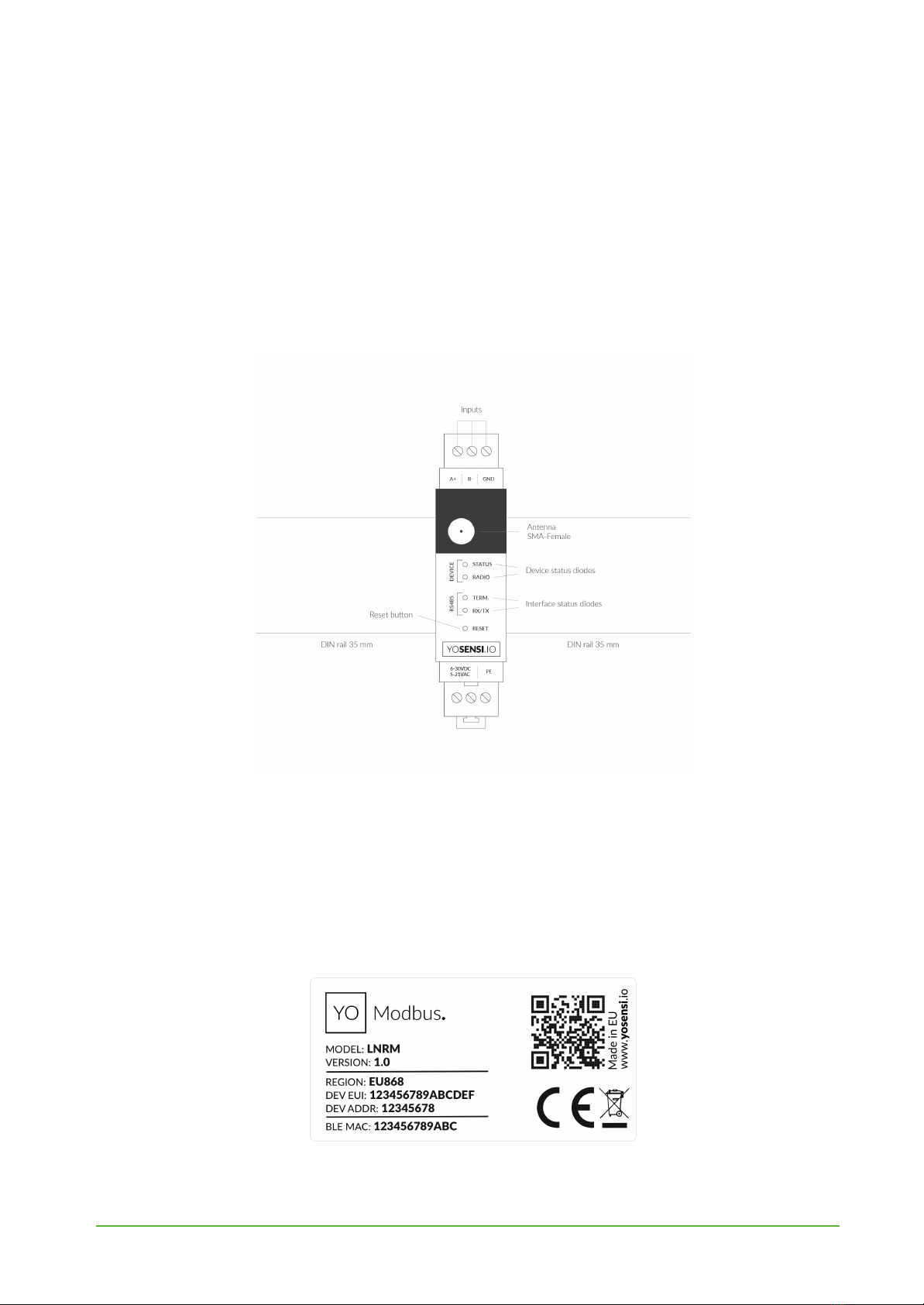
YO Modbus bridges between the Modbus network and the LoRaWAN. It allows users to read data
via Modbus RTU from slave devices and to send it via LoRaWAN. One YO Modbus device provides
capacity to create up to 150 Modbus queries and to send them in up to 30 different LoRa packets.
These are sent in LoRA packets of up to 5 queries each (i.e. maximum of 30 packets).
Figure 1 Device top view.
Device sticker placed on the right side of the device enclosure contains information about model,
version, LoRaWAN region and 3 parameters important in case of device identification and
configuration:
-DEV EUI: 64-bit unique device identifier in a LoRaWAN network,
-DEV ADDR: address required to connect via ABP activation type to LoRaWAN,
-BLE MAC: bluetooth physical address.
Figure 2 Device sticker.
www.yosensi.io

YO Modbus User guide v2.1
page 5/33
Physical interfaces
LEDs
YO Modbus communicates its current behavior to the user by RGBW LED placed on the top of the
device shown on figure 1.
DIODE STATUES INTERPRETATION
BEHAVIOUR
COLOUR
DEVICE STATUS
Single flash
Green
General: device is working correctly (power and memory).
Single flash
Red
General: device is working incorrectly (power and memory).
LoRaWAN communication: failed to receive an
acknowledgement from LoRaWAN Server within specified
timeout.
Single flash
White
LoRaWAN communication: LoRaWAN packet sent \
confirmation from LoRaWAN Server after receiving the packet.
Slow flashing
Blue
BLE communication: connection to the device via BLE
(configuration).
Rapid flashing
Blue
LoRaWAN communication: connecting to LoRaWAN network.
Continuous lit
Orange
Term diode: Terminating resistor connected.
Rapid flashing
RS485
Red
RX/TX diode: RS485 packet sent
Green
RX/TX diode: RS485 packet received
Buttons
YO Modbus is equipped with one reset button under the interference status diode RX/TX shown on
the device top view. It is possible to press it with a thin pin.
www.yosensi.io

YO Modbus User guide v2.1
page 6/33
Figure 3 Connection the YO Modbus device with slave device.
RS485 interface
When connecting RS485 nodes to YO Modbus, connect the A+ line to the RS485 A bus and B− to the
RS485 B bus. GND connects to the ground terminal of the RS485 bus.
This device can be supplied with 6–30 VDC or 5–21 AC.
Optionally, a protective earth cable can be connected. To prevent loop currents, an Earth connection
should be made at only one point on the network.
Line topology may or may not require terminating loads depending on the length of cable used. The
impedance of the termination load should match with line impedance on both ends. The termination
load is usually 120 Ωon both sides, although the device contains an in-build terminating resistor RT.
YO Modbus communicates by sending queries to each device and converting polls, with data from
each slave, into LoRa frames for relay to the application server. Prior to communication between
nodes and the master, it is necessary to configure the serial transmission in the YO Modbus device.
For this, you will need to know the slave addresses and individual registers for reading data.
www.yosensi.io

YO Modbus User guide v2.1
page 7/33
Specifications
Physical
Figure 4 Dimensions of the device.
PHYSICAL SPECIFICATION
Dimensions
Height: 90 mm
Width: 17,5 (4 pole) mm
Depth: 58 mm
Colour
Light grey
Mounting method
35 mm DIN rail
Vertical (can be screwed to the wall)
Enclosure material
Polycarbonate
Fire resistance class
UL94-VO
Level of protection
IP20
Weight
90 g
www.yosensi.io

YO Modbus User guide v2.1
page 8/33
Operating conditions
OPERATING CONDITIONS
Temperature
0° to 70°C
Humidity
0 to 90%
Placement
Indoor use
Power supply
6 - 30 V DC
5 - 21 V AC
Power consumption
Typical: 12 mA DC (12 V DC)
Maximum: 120 mA DC (12 V DC)
Measured values
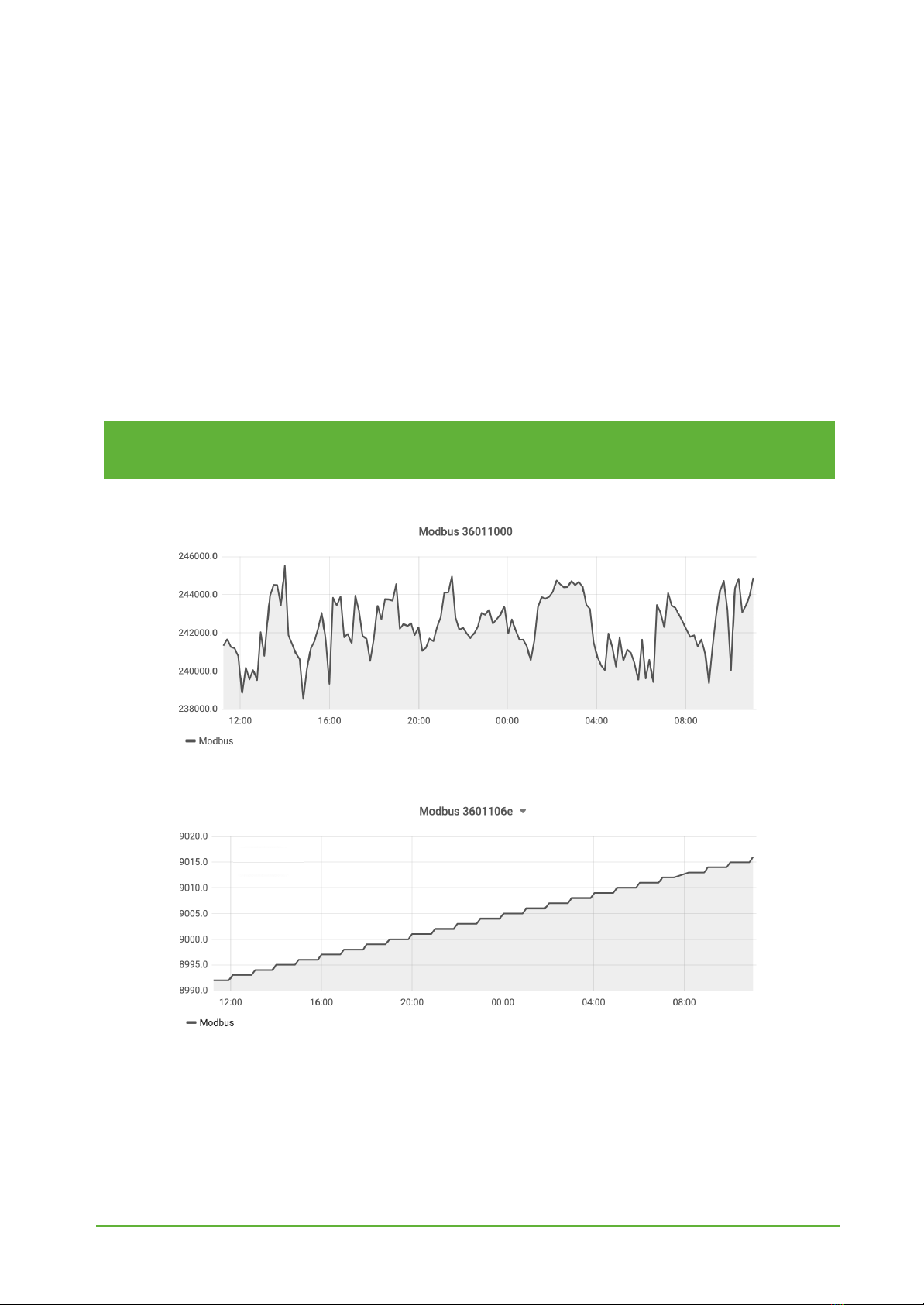
Internal voltage is used to monitor device condition to detect anomalies (like sudden drop) or its
current condition from voltage drop over time below the initial voltage rating.
Figure 4 Internal voltage chart.
www.yosensi.io
YO Modbus User guide v2.1
page 9/33
Queries and polls
YO Modbus can request up to 150 different queries from slave devices. Establishing communication
requires advance knowledge of the device’s starting registers, slave address and function codes. This
device supports the following read functions:
●01 (0x01) Read coils
●02 (0x02) Read discrete inputs
●03 (0x03) Read holding registers
●04 (0x04) Read input registers
The query data are read by Modbus RTU and sent by LoRaWAN. Each LoRa packet contains data
from the read registers. One LoRa packet can contain 5 five user-created polls, each up to 4 bytes.
NOTE
More information about queries and polls can be found in the device configuration
section.
Figure 4 Measurements from register 0x1000.
Figure 5 Measurements from register 0x106e.
www.yosensi.io
YO Modbus User guide v2.1
page 10/33
Installation
Package contents
1. Device.
2. Warranty card.
3. Antenna.
Safety precautions
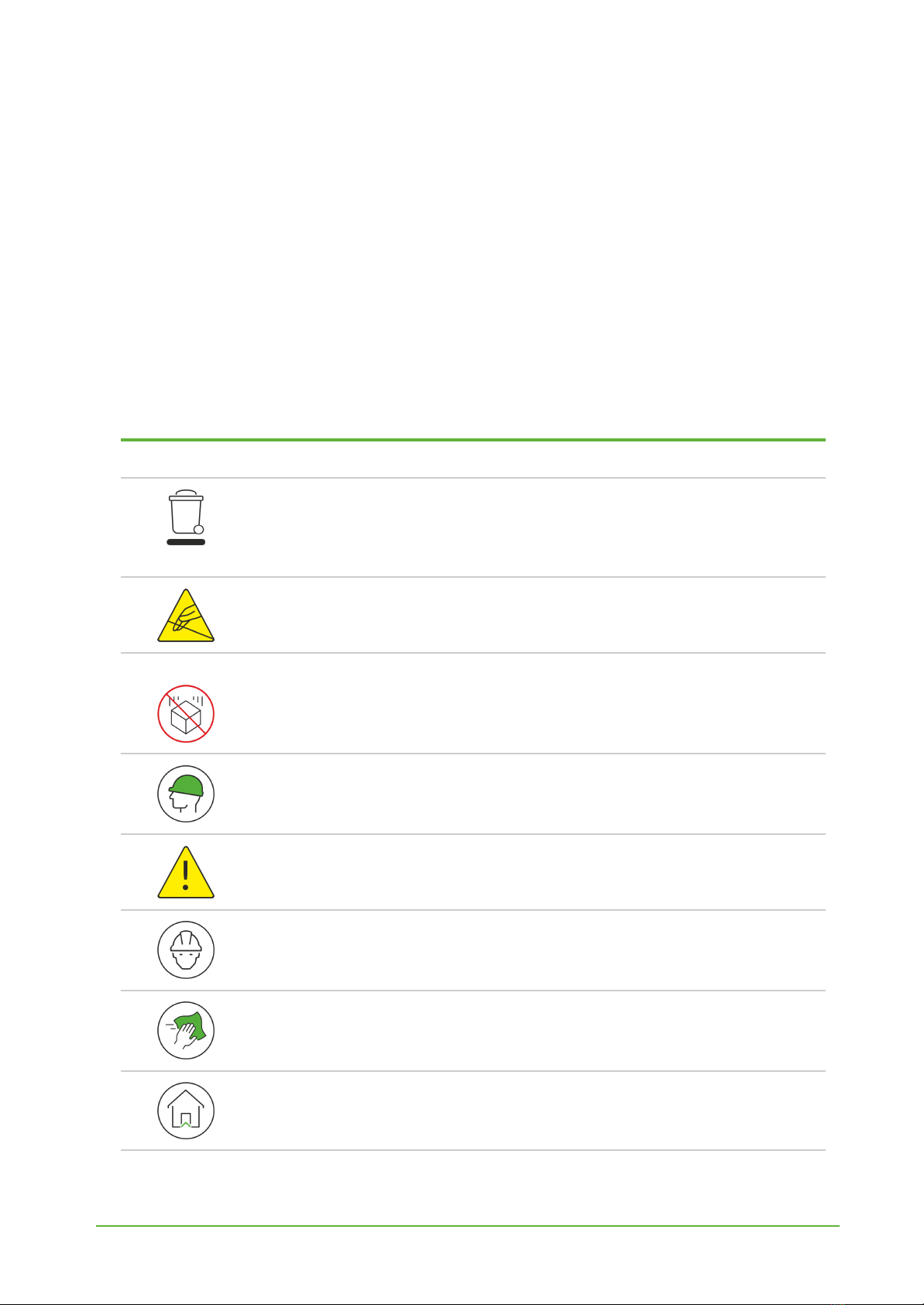
SAFETY PRECAUTIONS
SYMBOL
DESCRIPTION
Device is marked with a symbol saying that electrical and electronic
products may not be mixed with unsorted household waste. Remember
that batteries used to power the device must be treated at a specialized
treatment facility.
Remember about possible electrostatic discharge when replacing battery,
connecting input or doing some other operations near inside electronics.
Be careful while handling the device – dropping it may cause damage that will
affect the sensors and other electronics inside.
When installing the device on the wall remember to wear adequate protective
equipment.
To maintain the level of protection device cover screws must be properly
tightened. Device shouldn’t be used without cover.
Any actions inside the device's enclosure must be performed by trained
personnel only.
Clean the device only with damp cloth.
Device is intended for indoor use.
www.yosensi.io
Table des matières
Manuels Matériel réseau populaires d'autres marques

Matrix Switch Corporation
Matrix Switch Corporation MSC-HD161DEL Manuel utilisateur

B&B Electronics
B&B Electronics ZXT9-IO-222R2 Manuel utilisateur

Yudor
Yudor YDS-16 Manuel utilisateur

D-Link
D-Link ShareCenter DNS-320L Manuel utilisateur

Samsung
Samsung ES1642dc Instructions d'utilisation

Honeywell Home
Honeywell Home LTEM-PV Instructions de montage


