
Xinje XSA330-W Manuel utilisateur

XSA330-W
IoT Industrial controller
User manual [Hardware]
Wuxi Xinje Electric Co., Ltd.
V1.2 EN

This product and related documents are issued by Wuxi Xinje Electric Co., Ltd. in 2021, and all copyrights are
reserved. Product specifications are subject to change without notice. This document shall not be copied,
reproduced, translated or transmitted in any way or form without the permission of the authorized person. The
purpose of this document is to provide accurate and reliable information. Wuxi Xinje Electric Co., Ltd. will
not be responsible for the use of this manual or the damage to the rights and interests of third parties caused
by the use of this manual.
Please observe the following simple protective measures before using the
equipment to protect yourself and the product from injury:
Before using the equipment, be sure to disconnect the power supply to avoid
electric shock. Do not touch any components on the CPU or board when the
device is turned on.
Disconnect the power before making any hardware configuration changes.
Sudden electric shock when connecting jumpers or installing boards may
damage sensitive electronic components.
Note: According to Article 15 of FCC Rules, this equipment has been tested
and determined to conform to the Class A digital equipment standard. These
restrictions are intended to provide reasonable protection against harmful
interference to the operation of the system in a commercial environment.
This equipment will generate, consume and transmit radio frequency energy.
If it is not correctly installed and used according to the manual, it may cause
harmful interference to the equipment
1. Misuse may cause danger, personal injury or serious injury, and may
cause serious property loss.
2. Do not install and use the damaged IoT industrial controller, the IoT
industrial controller without parts, or the IoT industrial controller
whose model does not meet the requirements. There is risk of injury.
3. Please design a safety loop outside the IoT industrial controller to
ensure that the whole system can operate safely even if the circuit is
abnormal. Risk of causing malfunction.
Electrostatic
protection
FCC
Attension

4. Do not bind the controller wiring and power wiring together. In
principle, they should be separated by 10cm. Misoperation and product
damage may be caused.
1. Please install and use this product under the environmental conditions
specified in the general specifications of the manual. Do not use it in
damp, high temperature, places with dust, smoke, conductive dust,
corrosive gas, combustible gas, vibration and impact. It may cause
electric shock, fire, misoperation, product damage, etc.
2. Do not directly touch the conductive part of the product. It may cause
malfunction.
3. Please use the matching DIN rail to fix the product and install it on a
flat surface. Incorrect installation may cause misoperation and product
damage.
4. When processing the screw hole, please do not let the cutting powder
and wire chips fall into the product shell. It may cause malfunction.
5. When connecting the expansion module with the expansion cable,
please make sure that the connection is tight and the contact is good. It
may lead to poor communication and misoperation.
6. When connecting peripheral devices, expansion devices, batteries and
other devices, be sure to power off. It may cause malfunction.
7. Do not disassemble or assemble this product without authorization. The
product may be damaged.
8. Please plug and unplug the connecting cable when the power is off. It
may cause damage to the cable and misoperation.
9. When disassembling the expansion device, peripheral device and
battery, please disconnect the power first. It may cause misoperation,
failure, etc.
10. When the product is discarded, please treat it as industrial waste
Notes

1. Please correctly connect the AC or DC power supply to the special
power terminal of IoT industrial controller. The controller may be burnt
due to the wrong power supply. Before wiring the controller, be sure to
disconnect all external power supplies. Risk of electric shock.
2. Please use a 2mm2 wire for the third grounding of the grounding
terminal of the controller and expansion equipment, and do not share
the grounding with the strong current system.
3. Do not conduct external wiring to the empty terminal. It may cause
misoperation and product damage.
4. When connecting terminals with wires, be sure to tighten them, and do
not let conductive parts contact other wires or terminals. It may cause
misoperation and product damage.
5. After the IoT industrial controller is powered on, do not touch the
terminal. Risk of electric shock.
6. Please do not wire or disconnect the terminal with electricity. Risk of
electric shock.
7. Before changing the program in IoT industrial controller, be sure to stop
the running program. Misoperation may be caused.
WUXI XINJE ELECTRIC CO., LTD. All rights reserved
This material or its contents shall not be copied, transmitted or used without explicit written permission.
Violators shall be liable for the losses caused. All rights provided in the patent license and registration
including utility modules or designs are reserved.
Statement of responsibility
We have checked that the contents of this manual are consistent with the hardware and software described,
because errors are inevitable, we cannot guarantee complete consistency. However, we will often check the
data in the manual and make necessary corrections in future editing. Welcome your valuable comments.
March, 2021
Danger

Catalog
Preface.....................................................................................................................................................7
1. Product overview ................................................................................................................................8
1. 1 Product features............................................................................................................................8
1.2 Model Composition and list..........................................................................................................8
1.2.2 Model list ...............................................................................................................................8
1.3 Description of each part ................................................................................................................9
1.3.1 XSA330-W series structure composition...............................................................................9
1.3.2 LED indicator light ................................................................................................................9
1.3.3 Shut down button .................................................................................................................10
1.3.4 Reset button..........................................................................................................................10
1.3.5 Power supply input...............................................................................................................10
1.3.6 DP interface.......................................................................................................................... 11
1.3.7 Ethernet interface (LAN) .....................................................................................................12
1.3.8 USB interface.......................................................................................................................13
1.3.9 Serial port.............................................................................................................................14
1.3.10 I/O terminals ......................................................................................................................15
1.3.11 Encoder ..............................................................................................................................15
2. Specification parameters...................................................................................................................16
2.1 General specification...................................................................................................................16
2.2 Performance ................................................................................................................................16
2.3 Dimension ...................................................................................................................................17
3. System composition ..........................................................................................................................18
3.1 system composition.....................................................................................................................18
3.2 Programming software................................................................................................................19
3.3 Unpacking inspection..................................................................................................................19
3.4 Packing list..................................................................................................................................20
3.5 Production installation ................................................................................................................20
3.6 Power supply...............................................................................................................................21

3.6.1 DC power supply .................................................................................................................21
3.6.2 Power supply wiring ............................................................................................................21
4. I/O .....................................................................................................................................................22
4.1 Input specification.......................................................................................................................22
4.2 Encoder high speed counter input...............................................................................................24
4.3 Output specification ....................................................................................................................26
4.4 Transistor output processing .......................................................................................................26
5. BIOS setting......................................................................................................................................28
5.1 BIOS explanation........................................................................................................................28
5.1.1 CMOS setup.........................................................................................................................28
5.1.2 Function keys and auxiliary instructions..............................................................................28
5.2 Main menu ..................................................................................................................................29
5.3 Main (standard CMOS setting) ...................................................................................................31
5.4 Advanced BIOS setting...............................................................................................................32
5.5 Chipset setting.............................................................................................................................33
5.6 Security setting............................................................................................................................34
5.7 Boot setting .................................................................................................................................35
5.8 Save and exit ...............................................................................................................................36
5.9 Set COM port mode ....................................................................................................................37
6. Operation, commissioning and maintenance ....................................................................................38
6.1 Operation and commissioning.....................................................................................................38
6.2 Routine maintenance...................................................................................................................39
7. Q&A..................................................................................................................................................40

Preface
•Scope of application of the manual
This manual is applicable to XSA330-W series IoT industrial controllers and the specific models.
•Conventions in the manual
Due to space limitation, certain abbreviations may be used in the manual to replace the original
names. Now, these names that may be involved are listed in the table below for comparison.
Abbreviation
Explanation
XSA330-W
XSA330-W series IoT Industrial controller
Peripherals
Programming software, HMI, network module and other
equipment
Programming software
CoDeSys software

1. Product overview
1. 1 Product features
XSA330-W seriesis an IoT industrial controller for motion control based on X86+FPGA platform. It
uses Intel Apollo Lake multi-core processor, which can well support the stable operation of CoDeSys
core. Realize industrial level data security under the super capacitor power-off holding, and provide
customers with integrated and intelligent system solutions.
Features:
•Based on CoDeSys programming platform, support LD, FBD, IL, ST, SFC, CFC language
programming
•Based on EtherCAT bus control, it can be connected to 64 axis control system at most
•Support EtherNet/IP, OPC/UA, ModbusTCP and other communication protocols
•Two independent communication interfaces RS485 and RS232, which are convenient to operate
with traditional equipment
•TPM2.0 encryption, industrial data security
•Built in super capacitor to maintain power failure and ensure data security in case of abnormal
power failure
1.2 Model Composition and list
1.2.2 Model list
The specific model and description of XSA330-W series are shown in the table:
Model
Description
XSA330-W series
Intel ® Celeron ® J3455, memory 4G, hard disk 128G, 16X/16Y, 2-channel
USB2.0, 2-channel USB3.0, 2-channel Ethernet communication, 2-channel
EtherCAT communication, 2 sets of encoders, 2-channel RS232 or RS485
(BIOS control), 1 DP interface, Windows 10 system
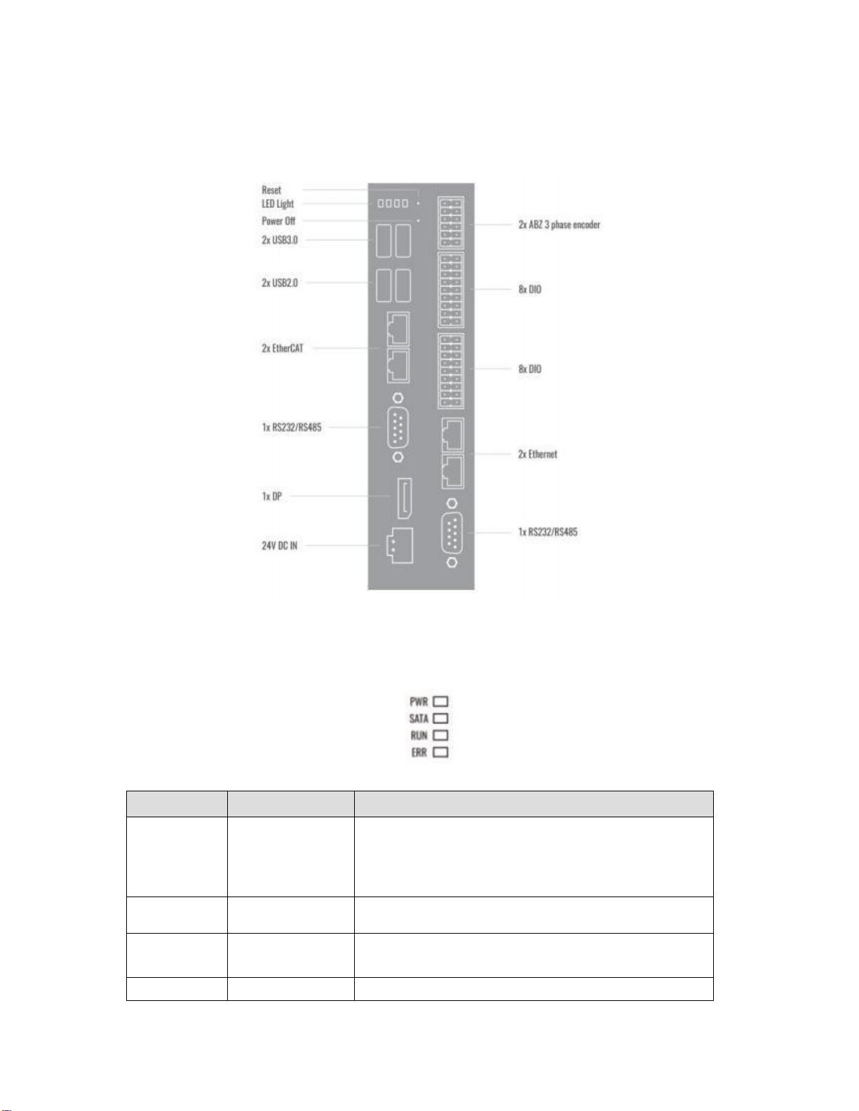
1.3 Description of each part
1.3.1 XSA330-W series structure composition
Figure 1-1 XSA330-W interface diagram
1.3.2 LED indicator light
XSA330-W seriespanel has 4 LED status indicators, as shown in Figure 1-2.
Figure 1-2 XSA330-W indicator light diagram
LED
Name
Description
PWR
Power supply
Shutdown: blue is normally on
The system works normally: green is normally on
The system does not enter or the system is abnormal: red is
normally on
SATA
SATA hard disk
detection
Data interaction: blue flashing/no data: off
RUN
Run indicator
Error (program exception Stop): off
Normal operation: green normally on
ERR
Error indicator
No error: Off

Yes (power off): red, normally on
1.3.3 Shut down button
XSA330-W seriesis equipped with a shutdown button (pinhole structure), which can be forced to shut
down by pressing for 4 seconds, as shown in Figure 1-3.
Figure 1-3 shut down button
1.3.4 Reset button
XSA330-W seriesis equipped with a Reset key (pinhole structure). Short press can restart the system.
Long press can reset the BIOS (clear CMOS) in power off status, as shown in Figure 1-4.
CMOS is powered by the button battery on the motherboard. Clearing CMOS will permanently erase
the previous system settings and set them to the original (factory setting) system settings. The steps
are as follows:
(1) Turn off the controller and disconnect the power supply
(2) Press the Clear CMOS key for 3-5 seconds with a slender pin, and then release it
(3) Start the controller, press the [Del] key to enter BIOS settings during startup, and reload the
optimal default value
(4) Save and Exit Settings
Figure 1-4 Reset button
1.3.5 Power supply input
XSA330-W seriesis equipped with a 24V 4PIN phoenix terminal, as shown in Figure 1-5.
Please use the adapter or switching power supply provided with the device, and do not connect the
power supply with a voltage exceeding 25.2V, otherwise the motherboard will be burnt due to
overvoltage.
Figure 1-5 power supply input interface
Table des matières
Autres manuels Xinje Contrôleurs


