x-net SG9224B Manuel utilisateur

1
24-Port Fast + 2-Port Giga
Intelligent Ethernet Switch
SG9224B
WEB USER GUIDE
Date: 02, 2004
Standard Version
Version: 1.02
1

2
I. Table of Contents
1. Introduction
1-1. SG9224B with ARM S3C4510X01 Hardware Specification .……………………………. 5
1-2. SG9224B Management Software Specification ………………………............................5
1-3. System block diagram.............................…………………………………………..............6
2. Web Management Function.................................................................…………………….7
2-1. Default Web Operation..............................................................………………………….7
2-2. Web Management Home Overview ............................................………….....………... 8
2-3. Web Sitemap ..........................................………...........................…………………….. 10
2-4.System management function ............................................................. ……………….. 10
A. System Login...........................……….........................................................................10
B. 802.1x configuration ........................................….......................................…………. 11
B-1 802.1x Configuration
B-2 802.1x Misc Configuration
B-3 802.1x Per Port Configuration
C. Administrator...............................................................................................................14
C-1 Authentication Configuration
C-2 System IP Configuration
C-3 System Status
C-4 System Update Configuration
D. Configuration Backup..............................................................................………….… 17
D-1 TFTP backup configuration
D-2 TFTP Restore Configuration
E. DHCP Server ................................................................................................……….. 18
E-1 DHCP Server configuration
E-2 DHCP server Show IP Binding
E-3 Exclude IP Configuration
E-4 Pool Configuration
E-5 Static IP configuration
F. Firmware Update...................................................................................................…..21
F-1 TFTP Update Firmware
F-2 Web Update firmware
G. Forwarding and filtering.....................................................................................……..23
G-1 forward configuration
G-2 forwarding Table
G-3 Mac filter Configuration
G-4 Mac Static configuration
H.IGMP Snooping.........................................................................…………………..….. 26
2

3
H-1 IGMP configuration
I. Log ….......................................................................................……………………… 27
I-1 Event Log Configuration
I-2 Show Event Log
I-3 SysLog Configuration
J. NTP Management .....................................................................…………..………. 29
J-1 NTP configuration
J-2 System Time Configuration
K Port control ........................................................................................………....……. 30
K-1 Bandwidth Control configuration
K-2 Module Information
K-3 Port Control Configuration
K-4 Port Mirroring Configuration
K-5 Port Statistics
L. QOS configuration................................................................................………….........35
M-1 QOS Configuration
M. RMON Configuration...............................................................…………………..........37
M-1 Alarm Configuration
M-2 Event Configuration
M-3 History Configuration
M-4 Statistics Configuration
N. SNMP Management....................................................................……………..............39
N-1 SNMP Configuration
N-2 SNMP Trap Configuration
O. Spanning Tree………………………………………………………………………..……. 40
O-1 Spanning Tree configuration
O-2 Spanning Tree Port Configuration
P. Stack Management ……………………………………………………………..……….... 42
P-1 Stack Configuration
P-2 Stack Status
Q. System Reboot ............................................................................…..………............. 43
Q-1 System Reboot
Q-2 Update System configuration
R. Trunk Management..........................................................……………..…………...... 44
R-1 Show LACP Status
R-2.Trunk Configuration
S. VLAN Configuration................................................................…………......................47
S-1 802.1q VLAN
3

4
S-2 Port based VLAN
S-3 VLAN Disable
4

5
1. Introduction
SG9224B is a non-blocking high performance Ethernet switch engine, integrated with 24
ports of 10/100Mbps and two ports of 10/100/1000Mbps. Each port can be either
auto-sensing or manually selected via EEPROM initial configuration or CPU on-line setting
to run at 10Mbps or 100Mbps or 1000Mbps speed rate, full or half duplex mode, enable or
disable flow control capability, the detail advance feature see the manual.
1-1. SG9224B with ARM S3C4510X01 Hardware Specification
Content:
A. MAC
(1) Version: VT6526
(2) SRAM: Embedded 3Mbit packet memory and 1Mbit control memory.
(3) Store & Forward
(4) External 25MHz crystal only.
(5) VT6526 Chip Package: 208-pin LQFP
B. CPU
(1) ARM: S3C4510X01
(2) Flash ROM: 32Mbit with SNMP/VLAN
(3) SDRAM: 8Mbyte (512K Wordsx16Bitsx2Banks)
(4) OSC: 50MHz, Internal clock is SDCLK (50MHz)
(5) HDLC: Serial Comm. I/F, Console port x 1
1-2. SG9224B Management Software Specification
TCP/IP ARP, ICMP, IP, TCP, UDP
SNMP SNMP V1, VIA private MIBS, MIB
counters of groups 1,2,4,9
Web management server HTTP 1.0, CGI, SSI
Telnet server Telnet 1.0
Console Standard UART
Spanning tree protocol IEEE 802.1d
Two-Level priority Queuing IEEE 802.1p
Port-based VLAN (IVL) IEEE 802.1q
Protocol-based VLAN IEEE 802.1v
Trunk IEEE 802.3 ad
5

6
1-3 System block diagram
6
7
2. Web Management Function
2-1 Default Web Operation
2-1-1. Login: The SG9224B provides a Web browser to manage the switch, the default
Log in values as follows:
a. Default Login Value:
(1) IPAddress:192.168.2.1
(2) IP Sub network:255.255.255.0
(3) User Name:admin
(4) Password:system
2-1-2.Change your System Configuration:
a. Change the configuration you needs.
b. Follow the Session C-4. ”System Update configuration” and write to device’s system
memory.
c. Reboot the switch device.
7

8
2-2. Web Management Home Overview
2-2-1. This is a Web Browser Page.
2-2-2. The system has three frames to combine
1. Upper Frame (Logo & Port Status)
2. Left Frame (UNCTION MENU)
3. Middle Frame (Content)
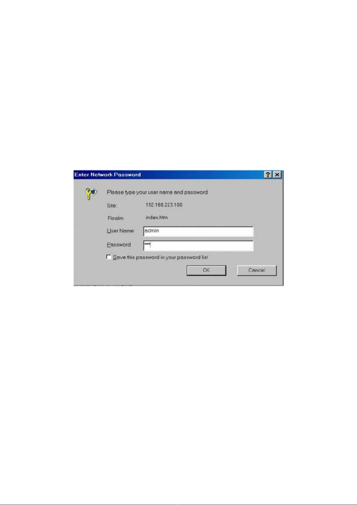
2-2-3. First logon the System, You should fill the correct ID & password.
8

9
2-2-4. Port status
This page can see per port status that click the upper switch’s banner.
1. State : Display port link status disable or enable. “No Link” will be treated
as “off ”.
2. Link Status: Display the current link status (Down or Link) of the port.
3. Trunking : Display the port whether in the Trunk mode.
4. TxGoodpkt: Display the transfer succeed package,.
5. TxBadPkt : Display the transfer failure package.
6. RxGoodPkt: Display the Received succeed package.
7. RxBadPkt : Display the Received failure package.
8. Port Security: Display the port security is enable or disable.
9. TxAbort : Display the Transfer abort package.
10.Collision : Display the collision result.
9

10
2-3. Web sitemap
There are many management functions, include:
2-4 System management function
a. System Login
Login the Web management
10
Table des matières
Manuels Routeur réseau populaires d'autres marques


NETGEAR
NETGEAR FS526T - Switch Manuel utilisateur

Korenix
Korenix JetNet 5710G Series Manuel utilisateur

Automated Logic
Automated Logic ZN551 Manuel du propriétaire

Cisco
Cisco ASR 1000 Series Manuel de l'opérateur

EnGenius
EnGenius ESR-9710 Manuel utilisateur

Cisco
Cisco 805 Series Instructions d'utilisation et de sécurité