Win PL-10600 Manuel utilisateur

User’s Manual
WIN Enterprises, Inc. Apr., 2009
1
PL-10600
Networking Appliance
1U Rack-mount Intel® 915GME/910GMLE Network Appliance
with 8 x GbE, 1 x FE, CF, SATA, LCM
User’s Manual
Version 1.0

User’s Manual
WIN Enterprises, Inc. Apr., 2009
2
© Copyright 2008, WIN Enterprises. All Rights Reserved
Manual Edition 1.0,Apr., 2009
This document contains proprietary information protected by copyright. All rights are reserved; no
part of this manual may be reproduced, copied, translated or transmitted in any form or by any means
without prior written permission of the manufacturer.
The content of this document is intended to be accurate and reliable; the original manufacturer assumes
no responsibility for any inaccuracies that may be contained in this manual. The original
manufacturer reserves the right to make improvements to the products described in this manual at any
time without prior notice.
Trademarks
IBM, EGA, VGA, XT/AT, OS/2 and PS/2 are registered trademarks of International business Machine
Corporation
Award is a trademark ofAward Software International, Inc
Intel is a trademark of Intel
RTL is a trademark of Realtek
VIA is a trademark of VIATechnologies, Inc
Microsoft, Windows, Windows NT and MS-DOS are either trademarks or registered trademarks of
Microsoft Corporation
All other product names mentioned herein are used for identification purpose only and may be
trademarks and/or registered trademarks of their respective companies
Limitation of Liability
While reasonable efforts have been made to ensure the accuracy of this document, the manufacturer
and distributor assume no liability resulting from errors or omissions in this document, or from the use
of the information contained herein.
For more information on PL-10600 or other WIN products, please visit our website
http://www.win-ent.com
For technical supports or free catalog, please send your inquiry to consultants@win-ent.com

User’s Manual
WIN Enterprises, Inc. Apr., 2009
3
Table of Contents
Chapter 1. General Information..............................................................................4
1.1 Introduction........................................................................................................4
1.2 Specifications.....................................................................................................4
1.3 Ordering Information.........................................................................................5
1.4 Packaging...........................................................................................................6
1.5 Precautions.........................................................................................................6
1.6 System Layout ...................................................................................................7
1.7 Board Dimensions..............................................................................................8
Chapter 2. Connector/Jumper Configuration .........................................................9
2.1 Connector/Jumper Location and Definition.......................................................9
2.2 Connector and Jumper Setting.........................................................................11
2.3 CompactFlashTM Card Socket Pin Define........................................................18
Chapter 3. Optional GbE Module & Riser Card Setting .......................................19
3.1 R-137: Ethernet module with four GbE Copper..............................................19
Chapter 4. BIOS Setup.........................................................................................20
4.1 Quick Setup......................................................................................................20
4.2 Entering the CMOS Setup Program.................................................................21
4.3 Menu Options...................................................................................................22
4.4 Advanced Menu...............................................................................................23
4.5 PCIPnP Menu...................................................................................................34
4.6 Boot Menu .......................................................................................................36
4.7 Security Menu..................................................................................................40
4.8 Chipset Menu...................................................................................................41
4.9 Power Menu ...................................................................................................44
4.10 Exit Menu .....................................................................................................46
Chapter 5. Utility & Driver Installation ...............................................................48
5.1 Operating System Support...............................................................................48
5.2 System Driver Installation ...............................................................................48
5.3 LAN Driver Installation...................................................................................49
Appendix A: Programming the Watchdog Timer .................................................50
Appendix B: System Resources............................................................................53
Appendix C: Cable Development Kit...................................................................57

User’s Manual
WIN Enterprises, Inc. Apr., 2009
4
Chapter 1. General Information
1.1 Introduction
The PL-10600 is a 1U rack-mounted hardware platform designed for network
service applications. Built with Intel Embedded IA components warranteed for
longevity, the PL-10600 supports Intel® Celeron M processor with the Intel
915GME/910GMLE chipset and ICH6-M I/O controller.
The platform supports high bandwidth DDRII SODIMM slot with memory up to
2GB. In order to provide the best network performance and best utilization, the
powerful storage interfaces include one 3.5" SATA HDD and CompactFlash™.
The optional onboard Cavium Nitrox Lite cn5xx security co-processor supports
multi-security protocol commands which can offload the CPU thus increasing
overall system throughput performance.
This platform affords four GbE Copper and max to 12 GbE Ethernet ports via
PCI-E by 1 or by 4 on front-panel. The front panel also has one FE
management port, one USB 2.0 port, one RJ-45 console port and LED
indicators that monitor power and storage device activities for local system
management, maintenance and diagnostics. In addition, the PL-10600
supports one PCI-E by4 slot, and is RoHS, FCC and CE compliant.
1.2 Specification CPU Intel® Pentium® M, Celeron® M Processors
Chipset Intel®915GME/ 910GMLE + ICH6-M
Front Side Bus 533/400MHz FSB
Processor System
BIOS AMI®512KB Flash BIOS
Technology Un-buffered and Non-ECC DDR2 533/400 MHz
memory
Memory
Capacity Up to 1GB with one SO-DIMM sockets
Expansion Expansion Slots one PCI-E x8 slot for expansion module
GbE Ethernet four RJ45 GbE ports, Intel 82574L, PCI-E x1
one RJ45 FE port, Intel 82562 PHY
four RJ45 GbE ports, Intel 82573L, PCI-E x1
(optional expansion module)
Ethernet
LAN bypass N/A
HDD one internal 3.5” SATA HDD bayStorage
Compact Flash
Socket
one CompactFlashTM Type I/II

User’s Manual
WIN Enterprises, Inc. Apr., 2009
5
USB one USB2.0 host connector
one internal 5x2 pin header (2-ports USB 2.0)
I/O
Serial one RJ45 Console port (COM1)
one internal 5x2 pin header (COM2)
Power Supply Watt AC open frame power supply
Form Factor 1U rack-mount
LCD Module one 16x2 LCM
Keypad four buttons keypad
LED one Power LED (Green)
one HDD LED (Yellow)
one Status LED (Green/Yellow via
programmable GPIO)
Dimension(W x D
x H)
440mm (W) x 270mm (D) x 44mm (H)
(17.3”W x 10.7”D x 1.7”H)
Operating
Temperature
Operating: 0 ~ 40°C ( 32 ~ 104°F )
Mechanical and
Environment
Humidity 5 ~ 95% relative humidity, non-operating,
non-condensing
Weight 1pc/CTN, 4.5kgs,
55cm(W) x 40cm(D) x 20cm(H)
Certification CE/FCC
1.3 Ordering Information
We offer some accessories for PL-10600 appliance for customer need.
PL-10600A-A 1U Rackmount Intel®915GME Network System, support Socket 479
CPU, 8x GbE, 1x FE, CF, SATA, PCI-E x8, LCM
PL-10600B-060-A 1U Rackmount Intel®910GMLE Network System, Celeron M 600MHz
CPU onboard, 4x GbE, 1x FE, CF, SATA, LCM
PL-10600C-060-A 1U Rackmount Intel®910GMLE Network System, Celeron M 600MHz
CPU onboard, 4x GbE, 1x FE, CF, SATA, Cavium CN505, LCM
R137A Expansion module with 4 RJ45 GbE ports, Intel 82573L
DK002 Cable development kit

User’s Manual
WIN Enterprises, Inc. Apr., 2009
6
1.4 Packaging
Check that the following items have been included in the package before
installation.
1. PL-10600 Appliance
2. Quick Installation Guide (Optional)
3. Cables (Optional)
4. CD-ROM that contains the following folders:
(1) Manual
(2) System Driver
(3) Ethernet Driver
(4) Utility Tools
If any of the above items are missing or damaged, please contact your dealer
or retailer from whom you purchased the PL-10600. Keep the box and carton
when you probably ship or store PL-10600 in near future. After you unpack the
goods, inspect and make sure the packaging is intact. Do not plug the power
adapter to the appliance of PL-10600 if it appears damaged.
Note: Keep the PL-10600 in the original packaging until you start installation.
1.5 Precautions
Please make sure you properly ground yourself before handling the PL-10600
appliance or other system components. Electrostatic discharge can be easily
damage the PL-10600 appliance.
Do not remove the antistatic packing until you are ready to install the
PL-10600 appliance.
Ground yourself before removing any system component from its protective
antistatic packaging. To ground yourself, grasp the expansion slot covers or
other unpainted parts of the computer chassis.
Handle the PL-10600 appliance by its edges and avoid touching its
components.
User’s Manual
WIN Enterprises, Inc. Apr., 2009
7
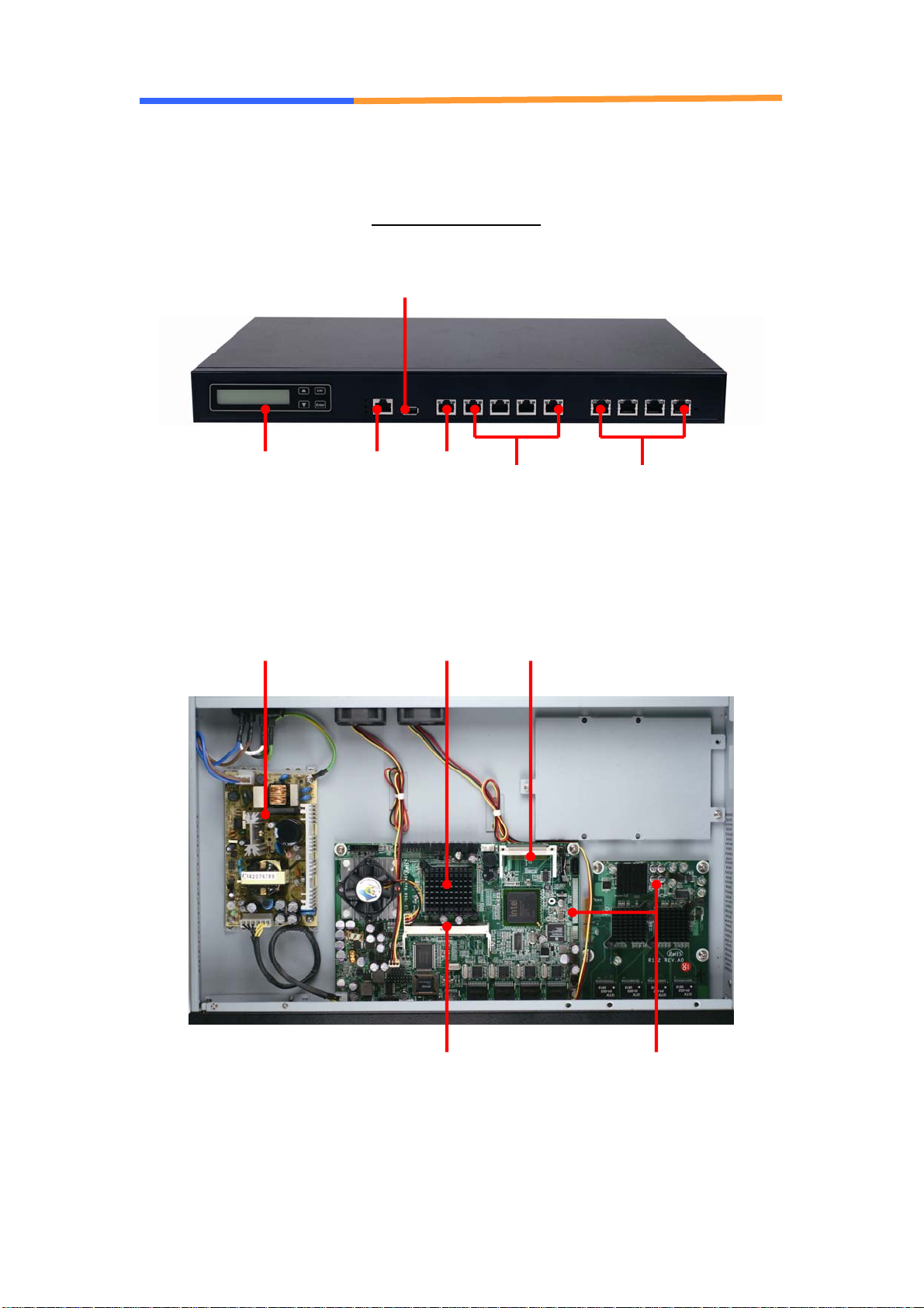
1.6 System Layout
PL-10600 Front Side
PCI-E slot &
Expansion Module
(optional)
CPU
DDR2 SO-DIMM
Power supply CF socket
10/100 4 GbE Copper
(optional module)
USB 2.0
RJ45
Console port 4 GbE
Copper
16x2 LCM & 4
buttons keypad

User’s Manual
WIN Enterprises, Inc. Apr., 2009
8
1.7 Board Dimensions

User’s Manual
WIN Enterprises, Inc. Apr., 2009
9
Chapter 2. Connector/Jumper Configuration
2.1 Connector/Jumper Location and Definition

User’s Manual
WIN Enterprises, Inc. Apr., 2009
10
Connectors Location:
Connector Description Connector Description
CN1 DDRII SO-DIMM CN2 LAN Port 1 (RJ45)
CN3 LAN Port 2 (RJ45) CN4 LAN Port 3 (RJ45)
CN5 LAN Port 4 (RJ45) CN6 LAN Port 5 (RJ45)
CN7 Reset Pin Header CN8 SATA Connector
CN9 None CN10 LPC Connector
CN11 Test Pin Header
(reserved for manufacture)
CN12 LCM Control Pin Header
CN13 LCM Connector CN14 COM1 Connector (RJ45)
CN15 COM2 Pin Header CN16 FAN Connector
CN17 FAN Connector CN18 FAN Connector
CN19 KB/MS Pin Header CN20 USB Connector (Port 0)
CN21 USB Pin Header (Port 1) CN22 VGA Pin Header
CN23 None CN24 Power Jack (+12V)
CN25 Power Connector
(2P or 4P)
CN26 PCI-Ex8 Connector
(CB-7968A Only)
PW1 SATA HDD Power
Connector
CF1 CF Socket
Connectors Location:
Jumper Description Jumper Description
JP1 Default (1-2)
Clear CMOS (2-3)
JP2
(CB-7968A
Only)
FSB 400 MHz (OPEN)
FSB 533 MHz (CLOSE)
Table des matières
Autres manuels Win Matériel réseau


Manuels Matériel réseau populaires d'autres marques

Matrix Switch Corporation
Matrix Switch Corporation MSC-HD161DEL Manuel utilisateur

B&B Electronics
B&B Electronics ZXT9-IO-222R2 Manuel utilisateur

Yudor
Yudor YDS-16 Manuel utilisateur

D-Link
D-Link ShareCenter DNS-320L Manuel utilisateur

Samsung
Samsung ES1642dc Instructions d'utilisation

Honeywell Home
Honeywell Home LTEM-PV Instructions de montage


