Wi-Tek WI-PMS310GF-Alien-I Manuel utilisateur

WI-PMS310GF-Alien-I QSG Page 1 of 21
WI-PMS310GF-Alien-I
8GE + 2 SFP
Layer 2 Managed PoE Industrial Switch Quick Start Guide
V2 0

WI-PMS310GF-Alien-I QSG Page 2 of 21
Table of Contents
1.
Introduction......................................................................................... 3
2.
Package Contents.............................................................................. 3
3.
System Requirements........................................................................ 3
4.
LEDs................................................................................................... 4
4.1
System LEDs............................................................................................ 4
4.2
RJ45 LEDs ............................................................................................... 4
4.3
SFP LEDs................................................................................................. 4
5.
Front Panel......................................................................................... 5
6.
Top Panel........................................................................................... 6
6.1
DC Inputs ................................................................................................. 6
6.2
Alarm Connections ................................................................................... 7
6.3
Other ........................................................................................................ 7
7.
Mounting Options ............................................................................... 8
8.
Configuration ...................................................................................... 9
8.1
Accessing the Configuration Interface...................................................... 9
8.1.1.
Graphical User Interface .................................................................................. 9
8.1.2.
Command Line Interface................................................................................ 10
8.2
Saving Current Configuration ................................................................. 11
8.3
DHCP IP Address................................................................................... 12
8.4
Network Time Client Setup..................................................................... 13
8.5
AAA ........................................................................................................ 15
8.5.1.
TACACS+ ...................................................................................................... 15
8.5.2.
802.1x (EAP).................................................................................................. 17
8.6
SNMP and MIBs..................................................................................... 18
9.
Firmware Update.............................................................................. 20
9.1
Update using GUI................................................................................... 21
9.2
Update using TFTP ................................................................................ 21

WI-PMS310GF-Alien-I QSG Page 3 of 21
1. Introduction
The WI-PMS310GF-Alien-I is a Managed, Layer 2 (L2), POE (24 & 48V) IP
Switch, with Gigabit Ethernet (GbE), Small Form-factor Pluggable (SFP), and
serial Console interfaces.
This document supplements the Wi-TeK Managed Industrial PoE
Switch User Manual, available for download from:
http://www.wireless-tek.com/Uploads/download/1583371174.pdf
2. Package Contents
WI-PMS310GF-Alien-I Temp/Humidity Sensor
3. System Requirements
Web Browser: e.g. Mozilla Firefox, Google Chrome, Safari, Microsoft
Edge, or Microsoft Internet Explorer.
Power supply. (Not included)
WI-PMS310GF-Alien-I QSG Page 4 of 21
4. LEDs
4.1 System LEDs
LED State Status
Blinking
(1 second)
Normal OperationPWR
Flashing
(Fast)
Initializing
Ring On Fast Ring Status
(EAPS: Ethernet Automatic Protection Switching)
V1 On DC (37 to 57 V) Power applied to V1 input
V2 On DC (37 to 57 V) power applied to V2 input, or
DC (12 to 57 V) power applied to
4.2 RJ45 LEDs
LED State Status
Off No network link‘Giga’
Green
Link Established
Flashing Indicates Activity
Green 48V PoE applied‘Link’
Yellow
24V PoE applied
4.3 SFP LEDs
LED State Status
Off No link9
10 Green Link established at 1000 Mbps (1 Gbps)
Flashing Indicates Activity

WI-PMS310GF-Alien-I QSG Page 5 of 21
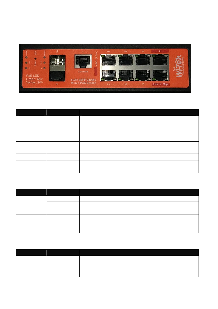
5. Front Panel
Port Description
Note Active PoE means that PoE voltage is applied only if a device is
connected.
RJ45 1-2 LAN: 100/1000 bps Ethernet connection
POE: Out. 4-Pair, Pins 1,2,4,5(+) 3,6,7,8 (-)
Software selectable:
•Off
•48 V Active 802.3at+ 30 W max
•48 V Active 803.3bt 60 W max
•Auto Active, Auto selection Off/48V PoE
RJ45 3-8 LAN: 100/1000 bps Ethernet connection
POE: Out. 2-Pair, Pins 4,5(+) 7,8 (-)
Software selectable:
•Off
•24 V Active
•48 V Active 802.3af 15 W max
•48 V Active 803.3at 30 W max
•Auto Active, Auto selection Off/24/48V PoE
SFP 9-10 Hot-swappable Small Form-factor Pluggable (SFP) ports
supporting 1 Gbps connections.
Console This port is compatible with Cisco part number 72-3383-01
(Console Cable). The serial settings are:
Baud rate: 38400
Data bits: 8
Stop bits: 1
Parity: None
Flow control: None

WI-PMS310GF-Alien-I QSG Page 6 of 21
6. Top Panel
6.1 DC Inputs
LED Input Comment
V1 and V2 Nominal 48 V DC
(37 ~ 57 VDC)
8A max
One or both can be active, allowing
redundant power supplies.
V3 12 to 57 VDC
10A max.
An alternative to V2. Wide voltage range
suitable for unregulated solar panel input.

WI-PMS310GF-Alien-I QSG Page 7 of 21
6.2 Alarm Connections
Alarm state is set based on both
•the IN+/IN- physical connection, and
•a number of software selectable internal triggers. See the
page.
Label Connection
IN+/IN- Monitoring of this input has these software selectable options:
•Close: No monitoring or action
•Low Level: Alarm is triggered if voltage below 5V, or
IN+/IN- are shorted together.
•High Level: Alarm is triggered if voltage above 5V
(max. 57V)
AL+/AL- This is a relay connection. Options are:
•Close: Always Closed
•Normally Closed: Open if Alarmed
•Normally Open: Closed if Alarmed
•Impulse: Repeated:
Closed 1 sec, Open 1 sec
6.3 Other
Label Connection
TMS Temperature & Humidity sensor. Use the supplied sensor.
Use is optional, but can be used as Alarm inputs.
RET To reset the Switch to factory defaults:
The Switch should be running after bootup is complete and
the PWR LED blinking. Press and hold the Reset button until
the PWR LED starts flashing rapidly. Release the Reset
button.

WI-PMS310GF-Alien-I QSG Page 8 of 21
7. Mounting Options
Use the built-in DIN rail, or Wall-mount options.

WI-PMS310GF-Alien-I QSG Page 9 of 21
8. Configuration
This section covers some tasks that are not fully covered in the User Manual
(see section Introduction, page13).
8.1 Accessing the Configuration Interface
There are two configuration options:
1. Graphical User Interface (GUI), using an Ethernet connection.
2. Command Line Interface (CLI), using a console cable.
8.1.1. Graphical User Interface
For full details, download this document:
http://www.wireless-tek.com/Uploads/download/1583371174.pdf
When in Factory Reset state, the Switch is set to use the default IP address
of 192.168.0.1.
1. Make sure that your host system is connected via Ethernet
to the Switch.
2. Configure the Ethernet adapter on your host system with a
static IP address in the 192.168.0.x subnet.
e.g. 192.168.0.10
3. Launch your web browser and type http://192.168.0.1
in the address field. Press enter (PC) or return (Mac).

WI-PMS310GF-Alien-I QSG Page 10 of 21
4. Enter the login credentials.
The default credentials are:
Username: admin
Password: admin
8.1.2. Command Line Interface
For full details, download these documents:
•https://ubwh.com.au/documents/WI-TEK_CLI.pdf
•https://ubwh.com.au/documents/WI-TEK_CLI_POE.pdf
(additional CLI commands for POE switches)
See an example session below, with many lines deleted for clarity.
Username:admin
Password:admin
Switch>?
Exec commands:
show Show running system information
Switch>show ?
ip Internet Protocol (IP)
Switch>show ip ?
interface IP interface status and configuration
Switch>show ip interface brief
Interface IP-Address Status Protocol
ge1/1 unassigned up down
Table des matières
Autres manuels Wi-Tek Changer

Wi-Tek
Wi-Tek WI-PMS310GF-UPS Manuel utilisateur

Wi-Tek
Wi-Tek FTTH ONU EQUIPMENT Manuel utilisateur

Wi-Tek
Wi-Tek WI-PS306GF-I Manuel utilisateur

Wi-Tek
Wi-Tek WI-PS518GF Manuel utilisateur

Wi-Tek
Wi-Tek WI-PCMS310GF Manuel utilisateur

Wi-Tek
Wi-Tek WI-PMS310GF-Alien Manuel utilisateur

Wi-Tek
Wi-Tek WI-PCES306G Manuel utilisateur


