Wascom EX 7 ES Manuel d'installation et d'exploitation
WARNING: ALL OPERATING AND MAINTENANCE PROCEDURES SHOWN ON THE NEXT
PAGE OF THIS MANUAL MUST BE FOLLOWED DAILY FOR PROPER OPERATION OF
YOUR WASCOMAT MACHINE.
PLEASE ENTER THE FOLLOWING INFORMATION AS IT APPEARS ON THE MACHINE(S)
DATA PLATE(S).
MAKE CERTAIN TO KEEP THIS MANUAL IN A SECURE PLACE FOR FUTURE
REFERENCE.
MACHINE TYPE OR MODEL
MACHINE SERIAL NUMBER(S)
ELECTRICAL CHARACTERISTICS:________ VOLTS, _______ PHASE, ______ HZ.
OPERATING & MAINTENANCE MANUAL
EX 7 ES – EX 10 ES
Emerald Series
471 1562-39/01
94.44

NOTICE TO: OWNERS, OPERATORS AND DEALERS OF WASCOMAT MACHINES
II
IMPROPER INSTALLATION AND INADEQUATE MAINTENANCE, POOR HOUSEKEEPING AND WILLFUL
NEGLECT OR BYPASSING OF SAFETY DEVICES MAY RESULT IN SERIOUS ACCIDENTS OR INJURY.
TO ASSURE THE SAFETY OF CUSTOMERS AND/OR OPERATORS OF YOUR MACHINE, THE FOLLO-
WING MAINTENANCE CHECKS MUST BE PERFORMED ON A DAILY BASIS.
1. Prior to operation of the machine, check to make certain that all operating instructions and
warning signs are affixed to the machine and legible. (See the following page of this manual
for description and location of the signs.) Missing or illegible ones must be replaced imme-
diately. Be sure you have spare signs and labels available at all times. These can be obtai-
ned from your dealer or Wascomat.
2. Check the door safety interlock, as follows:
(a) OPEN THE DOOR of the machine and attempt to start in the normal manner:
For coin-operated models, insert the proper coins to start the machine.
For manually operated models, place the ON-OFF switch in the ON position and
press the Start switch.
For FL and EX models, insert a program card, turn the starter knob to the Start
position and place the ON-OFF switch in the ON position.
For HI-TEK microprocessor models, turn the key switch to the RUN position, choose
a program and press the START button.
For SELECTA 28 models, select a wash program and press the Start button.
THE MACHINE(S) SHOULD NOT START !
(b) CLOSE THE DOOR to start machine operation and, while it is operating, attempt to
open the door without exerting extreme force on the door handle. The door should
remain locked!
If the machine can start with the door open, or can continue to operate with the door
unlocked, the door interlock is no longer operating properly. The machine must be
placed out of order and the interlock immediately repaired or replaced.(See the door
interlock section of the manual.)
3. DO NOT UNDER ANY CIRCUMSTANCES ATTEMPT TO BYPASS OR REWIRE ANY OF
THE MACHINE SAFETY DEVICES AS THIS CAN RESULT IN SERIOUS ACCIDENTS.
4. Be sure to keep the machine(s) in proper working order: Follow all maintenance and
safety procedures. Further information regarding machine safety, service and parts can be
obtained from your dealer or from Wascomat through its Teletech Service Telephone - 516/
371-0700.
All requests for assistance must include the model, serial number and electrical characteristics as
they appear on the machine identification plate. Insert this information in the space provided on the
previous page of this manual.
5. WARNING: DO NOT OPERATE MACHINE(S) WITH SAFETY DEVICES BYPASSED, REWIRED OR
INOPERATIVE! DO NOT OPEN MACHINE DOOR UNTIL DRUM HAS STOPPED ROTATING!
CAUTION
1. Do not open washer door until cycle is completed, operating
light is off, and wash cylinder has stopped rotating.
2. Do not tamper with the door safety switch or door lock.
3. Do not attempt to open door or place hands into washer to
remove or add clothes during operation. This can cause
serious injury.
MACHINE SHOULD NOT BE USED BY CHILDREN
PRECAUCION
1. No abra la puerta de la máquina lavadora sino hasta que la
máquina haya terminado su ciclo, la luz operativa esté apaga
da y el cilindro de lavado haya completamento terminado de
girar.
2. No interferia o manipule el switch o la cerradura de la puerta.
3. No trate de abrir la puerta o meta las manos dentro de la
máquina para meter o sacar ropa mientras la máquina está
en operación, pues puede resultar seriamento herido.
LAS MÁQUINAS NO DEBEN SER USADAS POR NIÑOS
SAFETY AND WARNINGS SIGNS
Replace If Missing Or Illegible
One or more of these signs must be affixed on each machine as indica-
ted, when not included as part of the front instruction panel.
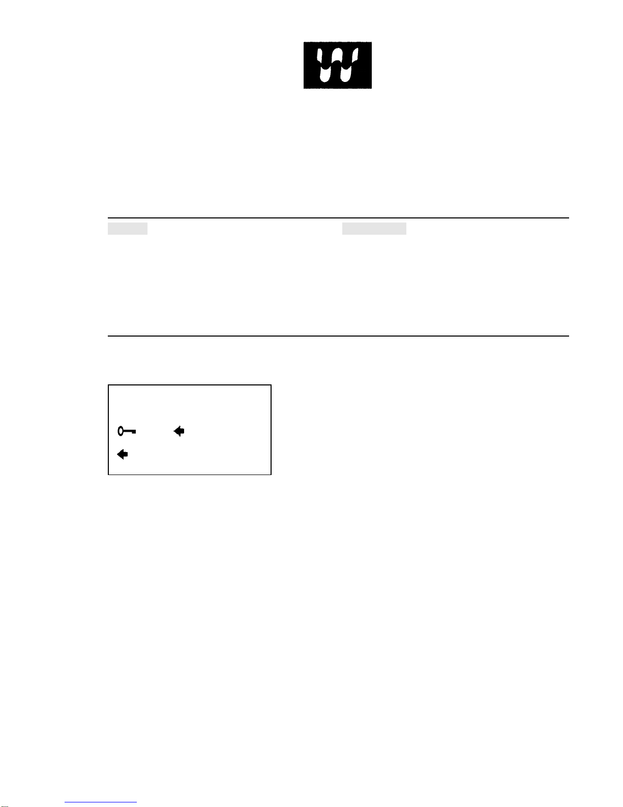
LOCATED ON THE OPERATING INSTRUCTION SIGN OF THE MACHINE:
LOCATED ON THE DOOR:
WARNING!
THE DOOR IS LOCKED A SHORT
WHILE AFTER THE SYMBOL AT
TURN TO
DOOR OPENING
– DRUM STAND STILL
–PRESS – PULL 471 7676-02
If you need to order more safety or warning
signs, call Wascomat's parts department at
516-371-2000, or call your local dealer.

Contents
Introduction ......................................................................1
Technical data.................................................................. 2
Installation........................................................................5
Safety rules .................................................................... 11
Operating instructions .................................................... 12
Programming..................................................................17
Wash cycles ................................................................... 21
Mechanical and electrical design ................................... 30
Maintenance................................................................... 47
Trouble-shooting ............................................................ 48
Service information ........................................................ 53
Safety instructions
• This machine is designed for water washing only.
• This machine must not be used by children.
• All installation operations are to be carried out by qualified
personnel. Licensed personnel are necessary for all electric
power wiring.
• The interlock of the door must be checked daily for proper
operation and must not be bypased.
• All seepage in the system, due to faulty gaskets etc., must be
repaired immediately.
• All service personnel must be fully familiar with the operating
manual before attempting any repair or maintenance of the
machine.
• This machine must not be sprayed with water, otherwise short
circuiting may occur.
• Fabric softeners with volatile or inflammable fluids are not to
be used in the machine.
The manufacturer reservs the right to make changes to design and
material specifications.
EX7, EX 10
1
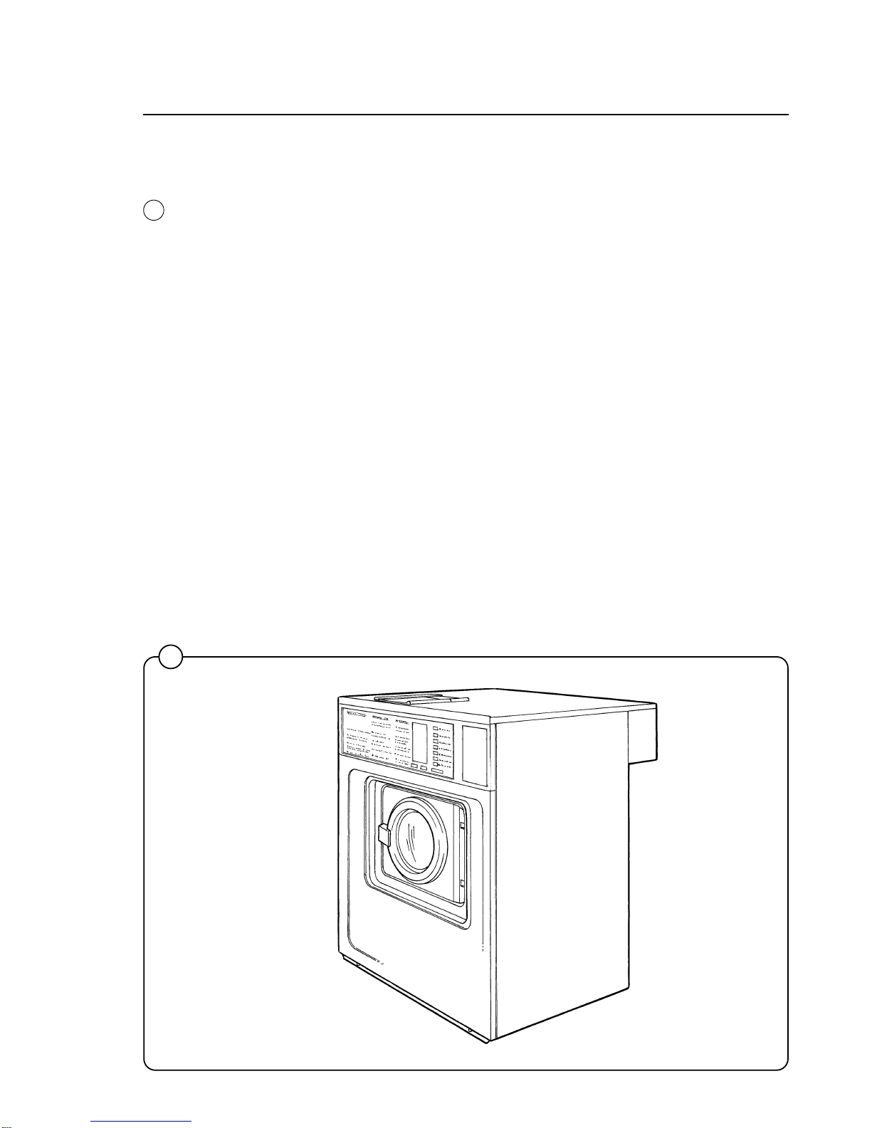
Introduction
Introduction
The EX 7 and EX 10 Emerald models washer/extractor with high spin
speeds, have been developed to meet the needs of state-of-the-art profes-
sional laundromats, institutions, hospitals etc., where high quality auto-
matic washing and quick formula variation are required.
Emerald models are unique because you can program different prices for
the seven wash cycles, giving the customer a real choice and allowing you
to maximize revenue by changing what each cycle is worth. In addition, you
can charge a higher price if the customer selects the Extra Extract option.
Using an external clock and wiring harness, these models may be pro-
grammed to lower the price by any percentage between any hours of any
days, for the ultimate in pricing flexibility!
The machines are free-standing, i.e. the drum is free to move relative to the
frame of the machine, being suspended from it by springs. This results in a
considerable reduction in vibration transferred to the frame of the machine,
which in turn simplifies installation: no special foundation is required.
The seven cycles offer different water temperatures, wash times, extraction
times, and normal or gentle drum rotation. EMERALD SERIES washers
achieve maximum environmental efficiency because only the minimum
amount of water is used for each cycle, which vary in duration.
When ordering spare parts or contacting Wascomat or your dealer for
service, always give the machine serial number, model, voltage and other
electrical characteristics appearing on the data plate at the top left of the
rear panel of the machine. The serial number is also printed on a sticker
inside the door...
KEEP THIS MANUAL IN A SAFE PLACE FOR FUTURE REFERENCE!
1821
1
Fig.
1

Technical data
2
Technical data EX 7
Dry load capacity up to 15 lbs
Overall dimensions Width 720 mm 28 11/32 in
Depth 660 mm 26 in
Height 1100 mm 43 5/16 in
Net weight 164 kg 361 lbs
Maximum floor load 1.64 ±0.7 kN 390 ±170 lbs force
Crated dimensions Volume 0.66 m323.3 cu.ft
Weight 176 kg 387 lbs
Inner drum dimensions Diameter 520 mm 20 15/32 in
Depth 310 mm 12 3/16 in
Volume 60 litre 2.1 cu.ft
Drum speed Wash 52 rpm
Distribution 80 rpm
Extraction 1020 rpm
G-factor During wash 0.8
During extraction 300
Motor speed During wash 1140 rpm
During distribution 1740 rpm
During extraction 3430 rpm
Voltage requirements 120 V 1-Phase 60 Hz
Rated output power Motor, wash 140 W 0.19 HP
Motor, distribution 100 W 0.13 HP
Motor extraction 350 W 0.5 HP
Overcurrent protection 20 A
Water connections Rec. pressure 2-6 kp/cm225-85 psi
Hose connection, water DN 20 3/4 in
Drain connection Hose 50 mm 2 in

Technical data 3
Technical data EX 10
Dry load capacity up to 25 lbs
Overall dimensions Width 720 mm 28 11/32 in
Depth 820 mm 32 9/32 in
Height 1100 mm 43 5/16 in
Net weight 225 kg 495 lbs
Maximum floor load 2.3 ±0.9 kN 550 ±220 lbs force
Crated dimensions Volume 0.77 m327.2 cu.ft
Weight 240 kg 528 lbs
Inner drum dimensions Diameter 520 mm 20 15/32 in
Depth 470 mm 18 1/2 in
Volume 100 litre 3.5 cu.ft
Drum speed Wash 52 rpm
Distribution 80 rpm
Extraction 1020 rpm
G-factor During wash 0.8
During extraction 300
Motor speed During wash 1130 rpm
During distribution 1730 rpm
During extraction 3400 rpm
Voltage requirements 120 V or 208-240 V 1- Phase 60 Hz
Rated output power Motor, wash 200 W 0.27 HP
Motor, distribution 180 W 0.24 HP
Motor extraction 550 W 0.74 HP
Overcurrent protection 20 A at 120 V
15 A at 208-240 V
Water connections Rec. pressure 2-6 kp/cm225-85 psi
Hose connection, water DN 20 3/4 in
Drain connection Hose 50 mm 2 in
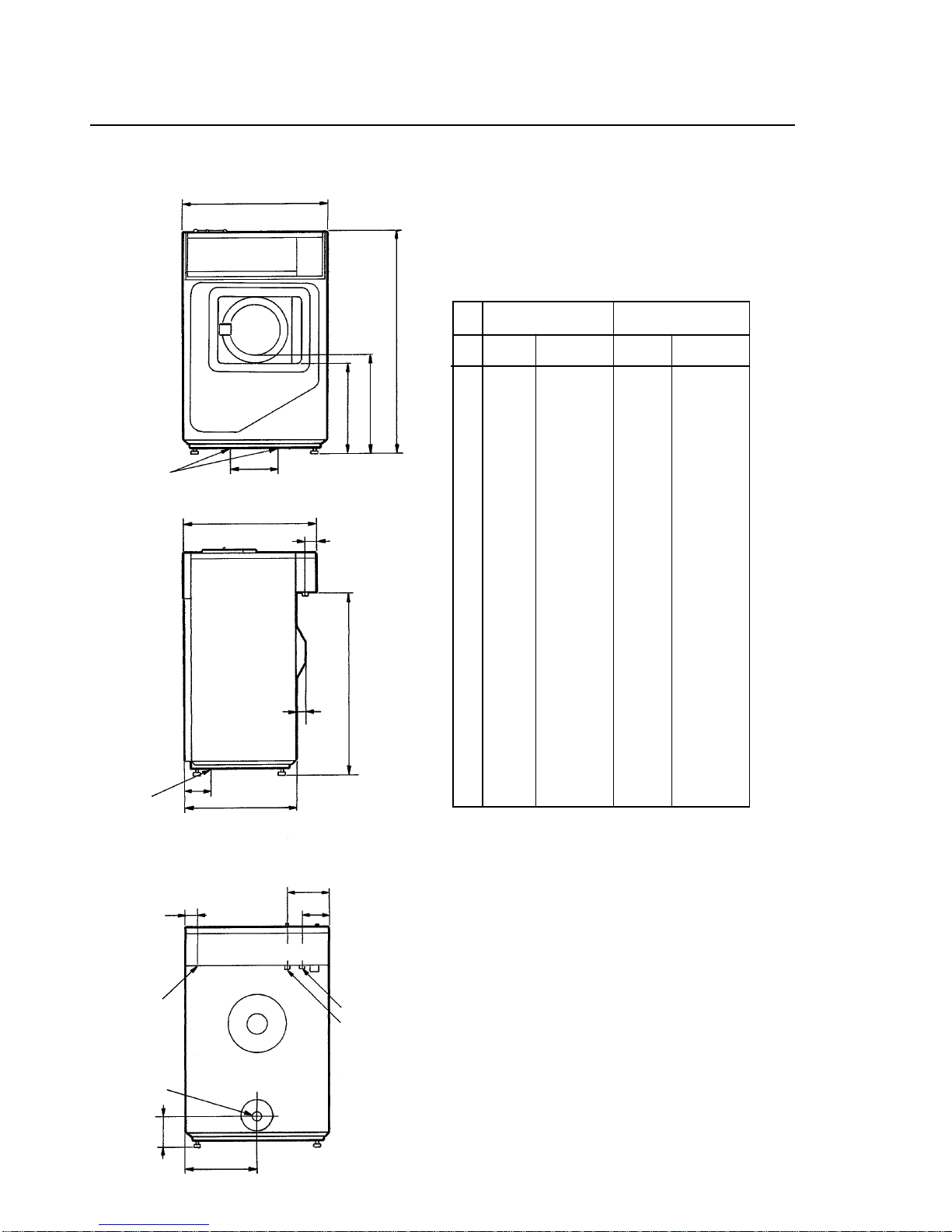
Outline and dimension
Technical data
EX 7 EX 10
mm inches mm inches
A 1100 43 5/16 1100 43 5/16
B 485 19 3/32 485 19 3/32
C 440 17 5/16 440 17 5/16
D 260 10 1/4 260 10 1/4
E 720 28 11/32 720 28 11/32
F 660 26 820 32 9/32
G 65 2 9/16 65 2 9/16
H 555 21 27/32 715 28 5/32
J 50 1 31/32 50 1 31/32
K 905 35 5/8 905 35 5/8
L 40 1 9/16 40 1 9/16
M 60 2 3/8 60 2 3/8
N 210 8 9/32 210 8 9/32
O 130 5 1/8 130 5 1/8
P 360 14 5/32 360 14 5/32
R 150 5 29/32 150 5 29/32
4
CBA
E
D
F
GH
JK
L
N
O
M
P
R
Drain
Electrical
connection
Mounting
holes
Mounting
holes
Hot water
Cold water
1596

Installation
2
0243
Installation
The machines are free-standing, i.e. the drum
can move relative to the frame of the machine.
This results in a considerable reduction in vibra-
tion transferred to the frame which in turn
simplifies installation: no special foundation is
required.
The machine is delivered complete with expan-
sion bolts, template etc. packed inside the drum.
Move the machine on its pallet to where it is to be
installed before removing the pallet retaining
bolts.
Location
Install the machine close to a floor drain or open
drain.
In order to make installation and servicing the
machine easier the following clearances are
recommended:
• At least 20" between the machine and the wall
behind
• and a minimum of 2" on both sides of the
machine whether installed next to the wall or
other machines.
Where space is limited it is possible to reduce
this distance to a minimum of 1" at the rear and
sides, since most service operations are carried
out from the front or top of the machine.
FloorThe floor must be able to withstand the following
loads:
EX7 EX10
static 390 lbs 550 lbs
dynamic 170 lbs 220 lbs
frequency of 17 kHz 17kHz
dynamic force
5
20"
2"
Fig.
2
Installation
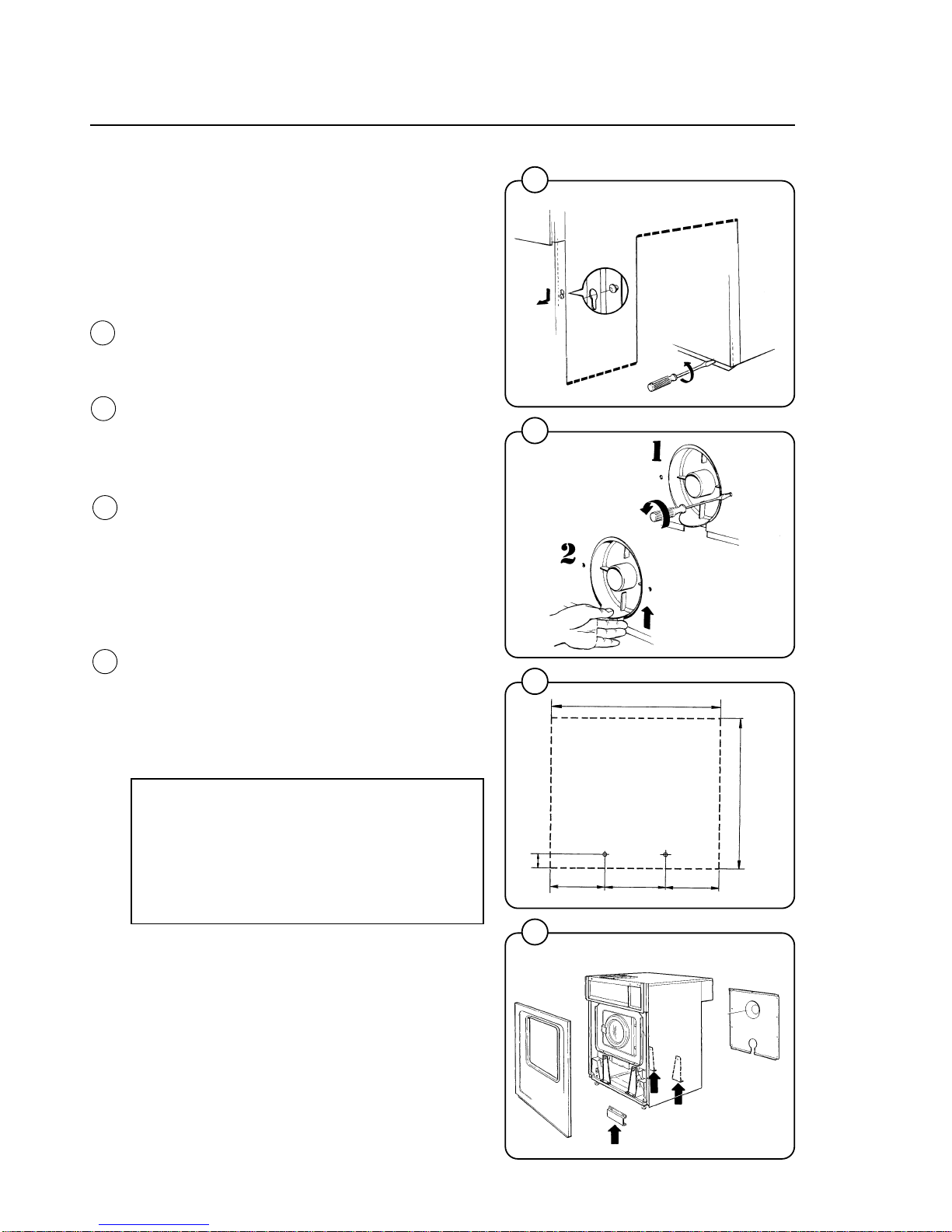
Mechanical installation
The machine is delivered with the drum locked in
place by four transport bolts fitted between the
frame and the drum. In orderto remove these
and install the machine, proceed as follows:
• Unpack the machine.
• Slacken off the screws in the lower edge of
the front cover plate and remove the plate by
pulling downward and outward to unhook it
from the chassis.
• Unscrew the retaining screws on the rear
plate and remove the plate. Remove the
drainage connection by unscrewing the two
screws. Lift the drainage connection upwards
until comes loose from the rear plate.
• Mark and drill two holes (diameter =5/16")
about 4" deep in the positions shown.
• Remove the machine from the transport pallet.
Fit the adjustable feet provided.
• Place the machine above the bolt holes you
just drilled. Always lift the machine by the
chassis, never by the door or door handle.
• Remove the four transport bolts securing the
drum to the chassis.
• Check that the machine is level and steady.
Adjust the level by using the four adjustable
feet (check first that they are screwed in as far
as possible). Lock the feet using the lock nuts
when the machine is satisfactorily positioned.
NOTE!
It is of utmost importance that the
machine be level, from side- to- side as
well as front- to- rear. If the machine is not
properly leveled, it may result in a false
out-of-balance cutout.
• Insert the expansion bolts supplied in the
holes drilled in the floor.
Fit the washers and nuts, and tighten well.
After the machine has been in use for a while
check and retighten the nuts if necessary.
3
4
5
6
0674
0244
0672
0671
6
EX 7
EX 10
720 mm
65mm 230mm 260mm 230mm
2 9/16 in
9 1/16 in 10 1/4 in 9 1/16 in
28 11/32 in
EX10:
820mm
32 9/32 in
EX7:
660mm
26 in
Fig.
3
Fig.
4
Fig.
5
Fig.
6
Ce manuel convient aux modèles suivants
1
Table des matières
Autres manuels Wascom Rondelle


