W&T Electronics 57661 Manuel utilisateur

W&T
Manual
Web-IO Analog-In/Out PoE
Type 10/100BaseT, 12-24V
Model 57661, 57662
Release 1.63, Jun 2010

W&T
© 06/2010 by Wiesemann & Theis GmbH
Microsoft, MS-DOS, Windows, Winsock und Visual Basic
are registered trademarks of Microsoft Corporation
Subject to errors and modifications:
Since errors are always possible, none of this information should
be used without checking. Please let us know of any mistakes or
unclear descriptions so that we can become aware of them and
correct them as quickly as possible.
Perform work on and with W&T products only as described here
and after you have read and fully understood the manual. Improper
use may result in hazardous conditions. We are not liable for
improper use. If in doubt, please check first with us or with your
dealer!

W&T
Introduction
The W&T Web-IO Analog-In/Out models include all the
functions in a single box for capturing your analog
measurements (0..20mA or 0..10V), tunneling them through the
network, saving and displaying them. A variety of alarm
functions are also available which can be custom added to your
own applications or into existing systems.
This manual contains all the information you need for
installation, configuration and operation of the Web-IO Analog-
In/Out devices..

W&T
Content
Introduction ............................................................................................ 3
1 Quick-start, Commissioning ......................................................... 7
1.1.1 Connect to power ................................................... 7
1.1.2 PoE supply ............................................................. 8
1.2.1 Wiring the in- and outputs ....................................... 9
1.3 Network connection ...................................................... 12
1.4 Assigning the IP address using „WuTility“ ....................... 13
1.5 Assigning the IP address using DHCP protocol ................ 15
1.5.1 Enabling/Disabling DHCP ...................................... 15
1.5.2 System Name ........................................................ 16
1.5.3 Lease-Time ........................................................... 17
1.5.4 Reserved IP addresses ........................................... 18
1.5.5 Dynamic IP addresses ............................................ 18
1.6 Start page ..................................................................... 19
1.7 Assigning the basic network parameters ......................... 21
2 Graphical Representation of the Measurements ..................24
2.1 Basic functions ............................................................. 24
2.2 Config-Menu ................................................................ 26
2.3 Table ............................................................................ 28
3 Other Basic Settings ....................................................................... 29
3.1 Configuring the port and device name ............................ 29
3.2 Specifying Output Mode ................................................ 32
3.3 Compensation of the output controller (57662 only) ....... 33
3.4 HTTP - Controlling outputs in the browser ...................... 36
3.5 HTTP - Controlling outputs using a command string ....... 37
3.6 HTTP - Polling inputs using a command string ................ 38
3.7 BINARY - Socket programs with binary structures ............ 39
3.7.1 Specifying the operating mode ............................... 40
3.7.2 The Web-IO Analog-In/Out as Socket-Server ............ 41
3.7.3 The Web-IO as Socket-Client .................................. 45
3.7.4 The Web-IO as UDP-Peer ........................................ 48
3.7.5 Password protection .............................................. 51
3.7.6 BINARY - The IO structures .................................... 53
3.7.7 Definition of the IO structures ................................ 54
3.7.8 Working with the IO structures ............................... 56

5
W&T
Subject to errors and modifications
3.8 Box-to-Box ................................................................... 60
3.8.1 Configuring the Slave Web-IO ................................ 60
3.8.2 Configuring the Master .......................................... 63
3.8.3 Determining Box-to-Box connection status ............. 67
3.8.4 Quitting Box-to-Box mode ..................................... 68
3.8.5 Quitting Box-to-Box mode only for the Slave Web-IO 69
3.9 OPC - Standardized access ............................................. 71
3.9.1 Installing the OPC-Server ....................................... 71
3.9.2 Uninstalling .......................................................... 72
3.9.3 Configuring .......................................................... 72
3.9.4 Configuring the Web-IO as an OPC device ............... 76
3.9.5 Program options ................................................... 79
3.9.6 Data model for OPC Data Access ............................ 81
3.9.7 OPC variables for Web-IO Analog ........................... 82
3.9.8 OPC Alarms & Events ............................................ 83
3.10 Local time setting ........................................................ 85
3.10.2 Summertime ............................................................. 86
3.11 Automatic time setting using a network time service ...... 88
3.12 Configuring the data logger ......................................... 89
3.13 Configuring the graphics output .................................. 91
3.13.1 Basic Settings ..................................................... 91
3.13.2 Select Sensor ...................................................... 94
3.13.3 Scale Config ....................................................... 95
3.14 Calibration .................................................................. 97
3.15 Browser access ........................................................... 98
3.16 Sending alarms via e-mail ............................................ 99
3.17 SNMP incl. alarm sending per Trap .............................. 108
3.18 Sending alarms per TCP (Client Mode) ........................ 112
3.19 Sending alarms per FTP (Client Mode) ......................... 113
3.20 Syslog messages incl. alarm sending .......................... 117
3.21 Time-based report ..................................................... 120
3.22 Check Alarm ............................................................. 120
3.23 ASCII command strings per TCP Port 80 ...................... 121
3.24 ASCII command strings per UDP ................................. 122
3.25 UP-/Download ........................................................... 123

W&T
4 Individual Measurement Polling ............................................ 125
4.1 Polling via TCP/IP ........................................................ 125
4.2 Polling via UDP ............................................................ 125
4.3 Polling via SNMP .......................................................... 126
5 Including Measurements in your own Web Page ............. 129
6 Data Logger .................................................................................... 134
7 Appendix ......................................................................................... 135
7.1 Alternative IP address assigning ................................... 135
7.2 Example for creating your own Web pages .................... 138
7.3 Firmware update ......................................................... 145
7.3.1 Where is the current firmware available? ................ 145
7.3.2 Firmware update over the network under Windows . 145
7.3.3 LED indicators .................................................... 147
7.4 Emergency access ....................................................... 149
7.5 Technical data ............................................................ 150
7.6 Disposal ..................................................................... 151

7
W&T
Subject to errors and modifications
1 Quick-start, Commissioning
To start up the W&T Web-IO Analog-In/Out and make it visible
in your network only a few steps are necessary.
1.1.1 Connect to power
If you want to use a power supply, connect 18-48V DC or 18-
30V AC to the screw terminal provided. Polarity is uncritical
when connecting AC power supplies. When connecting DC po-
wer supplies please note the polarity as indicated on the screw
terminal adapter:

8
W&T
To use the W&T model 11020 power supply, screw the power
supply plug into the screw terminal adapter:
1.1.2 PoE supply
The Web-IO Analog-In/Out can be used in PoE (Power-over-
Ethernet) environments in accordance with IEEE802.3af. The
supply voltage is provided then by the network infrastructure
through the RJ45 terminal. The device supports both phantom
power using data pairs 1/2 and 3/6 as well as power on the unused
wire pairs 4/5 and 7/8.
To enable power management for the supplying components, the
W&T Web-IO Analog-In/Out is identified as a Power Class 1 device
with a power consumption of 0.44 to 3.8W.
As an alternative to PoE the device can also be powered externally
using the screw terminal located on the underside of the device.
!Use of the W&T Web-IO Analog-In/Out is also possible in
networks wihtout PoE. In this casde simply use an external
power supply with the screw terminals as described above.
No additional configurations or settings are necessary.
9
W&T
Subject to errors and modifications
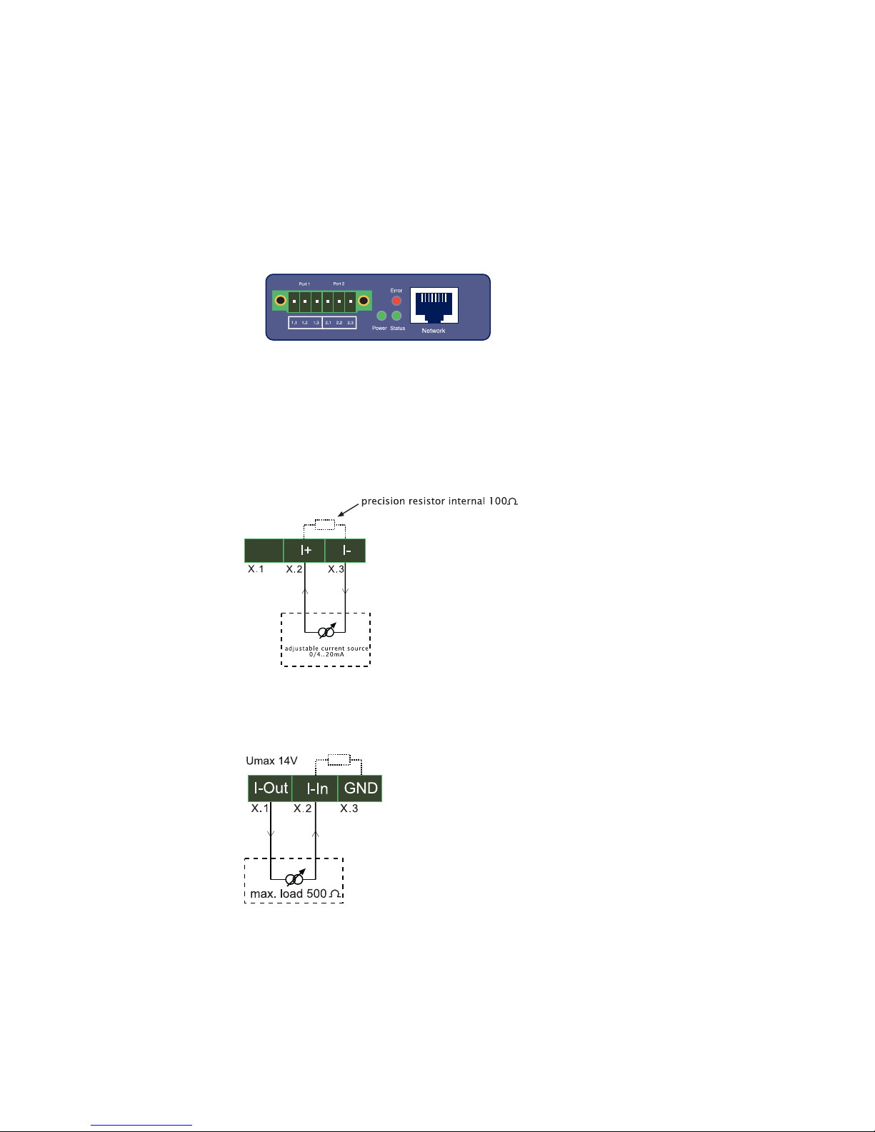
1.2.1 Wiring the in- and outputs
Depending on the configuration the W&T Web-IO Analog-In/Out
can be wired as follows, whereby Ports 1 and 2 are indicated by
an „X“. The configuration is identical for both ports:
1.2.2 Current input 0..20mA, passive (#57661)
1.2.3 Current input 0..20mA, active (#57661)

10
W&T
1.2.4 Current output 0..20mA (#57661)
1.2.5 Voltage input 0..10V (#57662)
1.2.6 Voltage output (#57662)
The voltage output must be jumpered to the Sense input, which
can be used to measure and regulate the output voltage. This
jumper can be made either directly on the device or at the remote
end. For longer cable distances the jumper should be made on the
remote end so that fluctuations are automatically compensated for.
Ce manuel convient aux modèles suivants
1
Table des matières


