Vutlan VT960i Manuel utilisateur

VT825i & VT825ii / Remote Monitoring Unit
Documentation page: https://vutlan.atlassian.net/wiki/spaces/DEN/pages/2713911301
/VT825i+VT825ii+Data+Center+Monitoring+Unit
Product page: https://vutlan.com/devices/162-55-vt825i-remote-monitoring-unit.html
Brochure: product version 1.2
Function and purpose
The unit is used for environmental monitoring (e.g. temperature, humidity, voltage, leakage, smoke, airflow). It is also used
as an I/O controller (e.g. door control, fans, generator, control panels, UPS, circuit breakers, alarms). Can use up to 1000
different elements - notifications, triggers, timers, logic schemes, sensors, dry contacts. Has built-in Web interface with virtual
sensors, logic schemes, different types of notification, and control panels. Has a slot for an LTE modem for an ethernet
connection reservation.
Two order options:
VT825i has only x1 power inlet.
VT825ii has x2 power inlets, providing a redundant power supply for A&B power distribution.
Order options / Dimensions
System Description
VT825i x1 230V AC power inlet.
VT825ii x2 230V AC power inlets, providing a redundant power supply for A&B power distribution.
VT825iDC x1 230V AC and x1 24-48V DC power inlets.
VT825DC x1 24-48V DC power inlet.
VT825DCDC x2 24-48V DC power inlets.

S
y
st
em
Diagram
V
T8
25i
V
T8
25
ii
V
T8
25
iDC
V
T8
25
DC
V
T8
25
D
C
DC
Physical Description
Front panel:
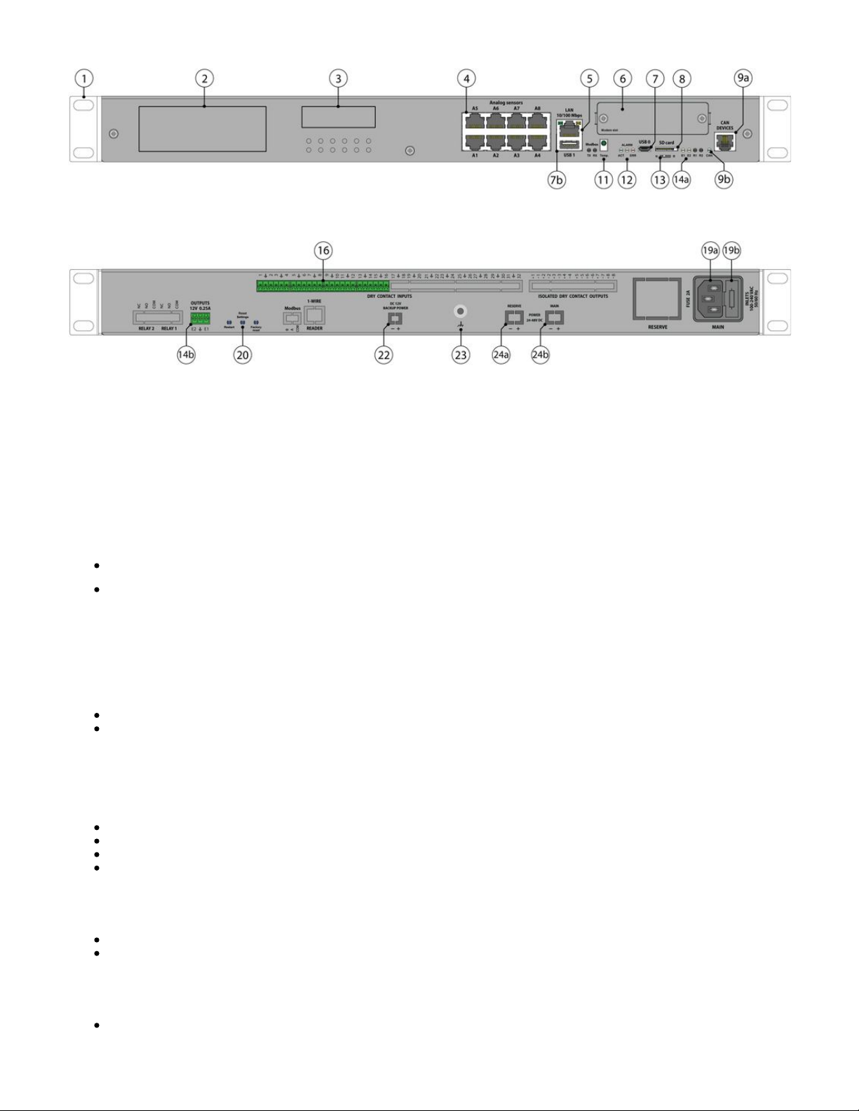
Back panel:
1. " " - x2 pcs for mounting brackets into a 1U 19" rack slot.1U 19 inch brackets
2. " " - Displays article number of the monitoring unit.Logo sticker
3. " " - A place for a sticker, can be used by a user to place an identifier of the system (for example, an IP Sticker space
address).
4. " .. " - 8 RJ12 analog sensor inputs with auto-sensing. Read instructions at " ",Analog sensors: A1 A8 Analog sensors connection
" ".Sensor configuration
5. " " - Ethernet 10/100 Base-T port, provides an Ethernet connection. Read more in this section "LAN port LAN, GSM, LTE,
".RADIUS, DNS, SSL, VPN
" " - orange LED for Ethernet port. It shows network traffic.Orange LED
" " - green LED for Ethernet port. It shows network traffic. Flashes green when the system starts up. Shows Green LED
the connection state (constant green light - the connection is established, blinking green - the connection attempt).
6. " " - " " can be installed in this slot. Modem slot VT790 / LTE slot modem
Read instructions This modem is ordered separately.
at "VT790 / LTE slot modem", "LAN, GSM, LTE, RADIUS, DNS, SSL, VPN".
7. USB ports are needed for USB camera recording, USB Flash for system logs, and for the system restore. Read instructions
at " ", " ", " ", "Connecting USB camera USB camera settings. How to save a video Saving system logs on USB flash drive USB
".upgrade or restore of default settings
a. " " - type micro USB-port 2.0, required to connect a USB camera.USB 0
b. " " - type USB-port 2.0, required to connect a USB camera or a USB Flash card.USB 1
8. " " - MicroSD card slot with an ejector. The card is needed for data storage or for the "system restore". Read SD card
instructions at " ", " ".Saving system logs to SD card Restore of the appliance (for VT960 series)
9a. " " - digital connector RJ12 for the connection of CAN sensors/extensions/devices on a CAN bus. Modules can CAN DEVICES
be chained together. Read instructions at " ", " ".CAN devises connection Setting up CAN
" " - green LED indicates CAN bus status.LED: CAN
The LED blinks slowly - nothing is connected
The LED blinks fast - configuration is in process
The LED glows constantly - connected to CAN devices
11. " " - accuracy +/- 1 °C.TEMPERATURE SENSOR
12. " " - green LED indicates appliance system status,LED: ACT
- operating mode of the device: switches at a frequency of 2 times per second;
- successful completion of the software update process: switches at a frequency of 4 times per second;
" " - The button can be programmed from the interface for alarm indicating.LED: ALARM
" " - red LED indicates error and traffic.LED: ERR
the operating mode of the device: If everything is normal, the LED is extinguished, if not - there's a constant glow;
software update mode: switches at a rate of 2 times per second;

software update mode: switches at a rate of 2 times per second;
13. " " Dip switch
Normal mode: The switch is switched to the left . The switch should be always in this position.
Recovery mode: The switch is switched to the right . Use this option only in case you need to recover manufacturing
settings.
14a. - 12V 0.25A (for each output) terminals outputs (electronic relay). Read instructions at ""OUTPUTS 12V 0.25A" Connecting
".12V devices to 12V outputs
" " - status indicators for two 12V 0.25A outputs.LEDs: E1, E2
The LED is ON (orange) - the output is ON (the initial state can be configured).
The LED is OFF (orange) - the output is OFF ((the initial state can be configured).
16. " " - Digital inputs (Type IN). Read instructions at " ", "DRY CONTACT INPUTS 1...16 Connecting dry contacts Dry contacts
".settings
19. Please refer to section "Order options" in this document.
18. - Reserve power inlet. 100-240VAC, 50/60Hz, Fuse 2A, Fuse 5x20mm, type C14."RESERVE"
19. " " - Power inlet. 100-240VAC, 50/60Hz, Fuse 2A, Fuse 5x20mm, type C14.MAIN
20. Buttons
9a. " " - the button restarts the appliance. Hold the button for 2 seconds and then let go, the system will restart.Restart
9b. " " - reset smoke sensors. Read more at .Reset settings Operation of smoke detectors in dusty conditions
9b. " " - reset settings to default factory settings.Factory reset
22. " " - optional order option. Only available for custom orders.DC 12V BACKUP POWER
23. " " - Chassis grounding, M4 thread. Enhances the immunity of the equipment against conducted and Chassis grounding
radiated RF disturbances. Please contact a professional electrician before connecting it.
24. " " - optional order option for some of the units. Please refer to section "Order options" in this document.POWER 24-48V DC
24a. - Reserve power inlet. 24-48V DC, 5.08mm 2EDGK power plug, 18-72VDC to 12VDC/0.84A"RESERVE"
24b. " " - Power inlet. 24-48V DC, 5.08mm 2EDGK power plug, 18-72VDC to 12VDC/0.84AMAIN
Connection overview diagram
The front panel of :VT825i & VT825ii

The back panel of :VT825ii
Drawing dimensions

Installing the device into a 19" rack
Use x3 pcs of supplied screws (M3 6mm) for each bracket to fix it on each side of the enclosure as shown in the picture below.
The screws and brackets are supplied with the unit.

Installing LTE slot modem
Product page: https://vutlan.com/modems/155-vt790-lte-slot-modem.html
Datasheet page: https://vutlan.atlassian.net/wiki/spaces/DEN/pages/2309947438/VT790+LTE+modem
Usage
Can be installed in VT855i v1.2, VT855ii v1.2, VT825i v1.2, VT825ii v1.2, VT960i v2, VT960ii v2 monitoring systems. (These
new systems are coming soon).
Description
4G LTE slot modem for Vutlan monitoring units. Allows to receive and send SMS messages. Provides Ethernet over 4G LTE.
Power-cycling is an embedded function.
Panel
VT825i v2.6, VT825ii v2.6, VT855i v2.6, VT855ii v2.6, VT960 v3 use VT740 LTE slot modem.

1.
2.
3.
4.
5.
" " - Connector, used when the modem is installed inside of the appliance to connect LTE auxiliary antenna. The Auxiliary
additional antenna helps to strengthen the signal level. (Auxiliary LTE antenna and antenna output are ordered
separately from the modem).
" " - displays modems status. Blinking = working.Status
"SIM card" - SIM card slot with an injector.
" " - Connector, used when the modem is installed inside of the appliance to connect GNSS antennaantenna
" " - Connector, used when the modem is installed inside of the appliance to connect GSM or LTE main Main antenna
antenna. (The main antenna is supplied together with the modem).
Installation
You can install the modem while the system is turned On. You may wait up to 3 minutes until the Telecom operator
information is renewed.
Step 1 1.1 Unscrew the two screws
holding the front panel called “Mo
”. Keep the screws, you dem slot
will need them in Step 3.
1.2 Take the panel out and put it
away.

Step 2 Plug the modem as shown on the
picture into the opening. The
board should slide into the guide
rails (marked as “1”) and plug
into the jack (marked as “2”).
Step 3 3.1 Use the screws we unscrewed
earlier and screw them in
clockwise, securing the new
modem in place.
3.2 Plug in the SIM card. The SIM
card slot has an injector.
Step 4 4.1 Screw the main LTE antenna
into “ ” jack.Main” antenna
4.2 If you want to strengthen the
signal, you can plug the second
auxiliary antenna into “ ” Auxiliary
jack.
Step 5 You are ready to go! Turn on the
system.
If you want to unmount the modem, you can unscrew the screws and just pull it out using x2 gold-plated antenna jacks.
Configuring the modem
Please read the following section for the configuration instructions:

Online documentation page link: Setting up a modem
The direct page link for users with paper documentation:
https://vutlan.atlassian.net/wiki/spaces/DEN/pages/1016347/Setting+up+a+modem
Inventory
Make sure that the contents of the delivery meet the following configuration. Report a missing or damaged component to your
supplier. If damage occurred during transportation, contact the appropriate delivery service.
Package content Description
Quantity
VT825i VT825ii VT825iDC VT825DC VT825DCDC
1 Monitoring unit VT825i. 1 pc
2 OTG Micro USB cable adater 1 pc
3 RJ-45 3m patch cable.
For LAN Ethernet connection.
1 pc
Autres manuels pour VT960i
1
Ce manuel convient aux modèles suivants
9
Table des matières
Autres manuels Vutlan Instrument de mesure


Manuels Instrument de mesure populaires d'autres marques


Endress+Hauser
Endress+Hauser Proline Promag 50 Caractéristiques techniques

Siemens
Siemens SITRANS F Coriolis FCT030 Manuel de la liste des pièces

KLINGER
KLINGER CMF V Series Manuel utilisateur

EXFO
EXFO FTB-2 Manuel d'exploitation et d'entretien

Keysight
Keysight M8290A Manuel utilisateur

ADTEK
ADTEK MW-5 Manuel utilisateur