Volvo ECR 58 Manuel utilisateur
2018-03-12
_6909
2200397 0000
Volvo ECR 58 & 88 D
Control System - ICS
Translation of the Original Instructions _EN
© Rototilt Group AB 2018-03-16
5
23
1
64
7
EN English
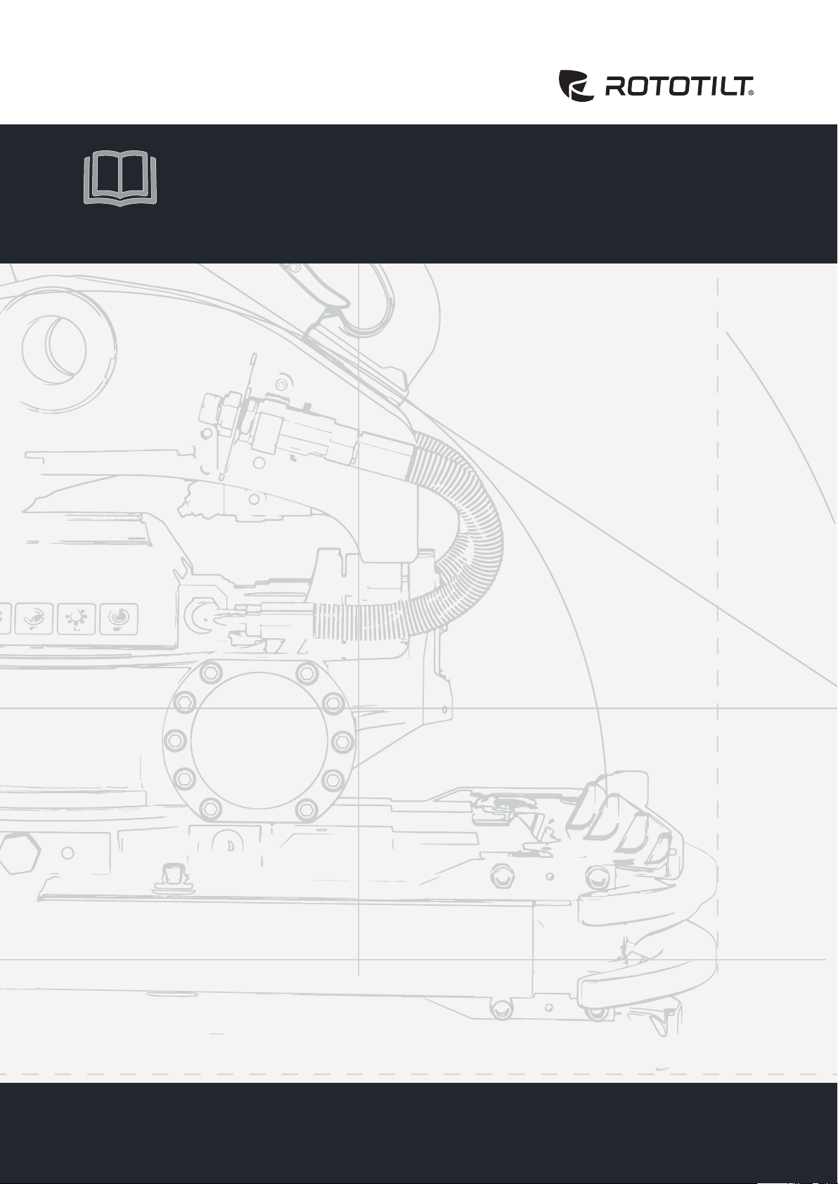
Overview
The product described in the document consists of components for the ICS control system. The overviews
show standard equipment and options.
Refer to the gures and lists below as well as on the following pages.
ICS control system
ICS control system consists of the
following components:
1. Harness, boom
Contact (SecureLock, machine
coupler)
Contact with safety plug
2. Display
Switch for tool replacement.
Cab control unit, CCU
3. Handles with controls to operate
Rototilt®functions and base machine
functions are ordered separately
4. Valve block
Electric swivel
5. Rototilt®control unit, TCU
Zero-position sensor. (ICS sensor,
ICS SecureLock)
Frequency sensor. (ICS sensor,
ICS SecureLock)
6. Connection to the base machine
control unit.
7. Locking cylinder sensor.
(ICS SecureLock)
LED lighting. (ICS SecureLock)
!
IMPORTANT - Read the Instructions for Use for the
control system, tiltrotator and base machine before
starting work. Pay particular attention to the safety
instructions.
!
IMPORTANT - Pressurising the Rototilt®hydraulic
system means that the quick coupler locking
function will be pressurised.
!
IMPORTANT - Connected safety plug ensures that
the base machine’s quick coupler is not opened
accidentally during use of the tiltrotator.
2200397_ _6909
© Rototilt Group AB 2018-03-16
!
PULSATING
LIGHT
FIXED
LIGHT
TCU
CCU
Sound
Light
Power
CAN-bus
Internal
Error
LED INDICATIONS
OK Error
EN English
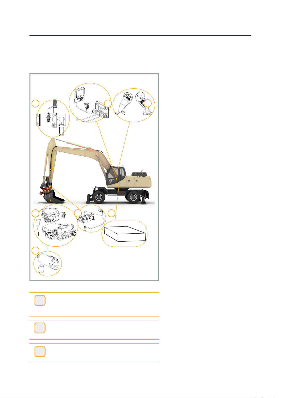
Control unit
The control units have three LEDs:
green, orange and red. When the system
is working correctly, all LEDs light and
with no ashing.
When a malfunction occurs the relevant
LED begins ashing.
PWR (green) shows whether the unit is
powered up.
CAN (orange) shows whether communi-
cations with CAN bus are working.
SYS (red) shows whether the unit’s inter-
nal components are working correctly.
The control units are not interchangeable.
Cab control unit, CCU
The control unit receives signals from the
handles and switches.
The control unit sends signals to the
valve block shunt and tiltrotator via CAN
bus.
Rototilt® control unit, TCU
The control unit receives signals from
the cab control unit, and from sensors in
Rototilt®.
Rototilt® control unit sends signals to
valves and LED lamp.
There is a sensor in the Rototilt® control
unit that detects the tilt angle.
!
IMPORTANT - The control units have a similar
appearance but the content differs. They are not
interchangeable.
Display
Settings, calibration and activation of
certain functions are made via the display
and its keys.
There is a buzzer in the display that
sounds to attract the operator’s attention
if the quick coupler locking function is
open or in the event of a fault.
Switch, quick coupler locking
function
The quick coupler locking function switch
is interlocked. This prevents accidental
activation of the quick coupler locking
function.
!
WARNING! A problem has occurred if the buzzer
sounds without activating the quick coupler locking
function switch. The display shows information
about the current problem.
2200397_ _6909
© Rototilt Group AB 2018-03-16
Right
Left
B
2
A
1
Control Unit -
Excavator
C
D
EN English
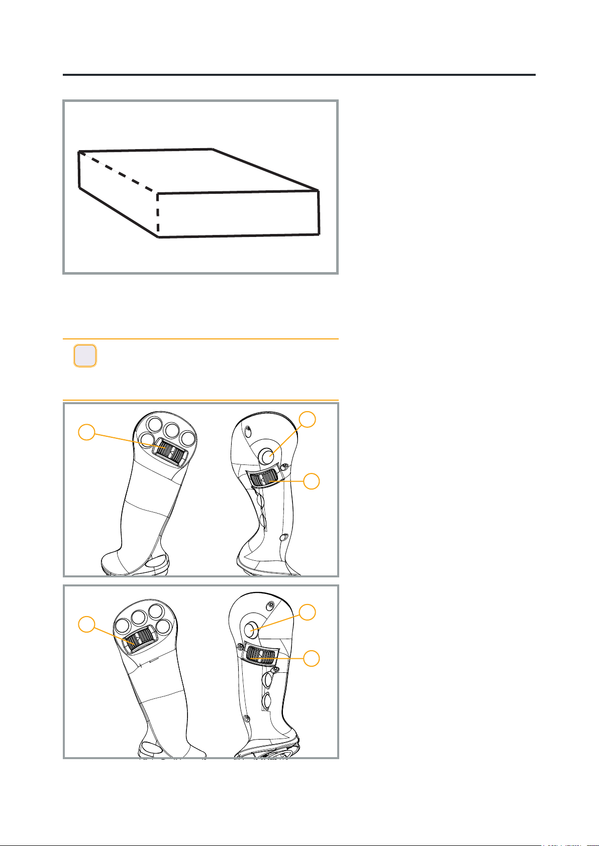
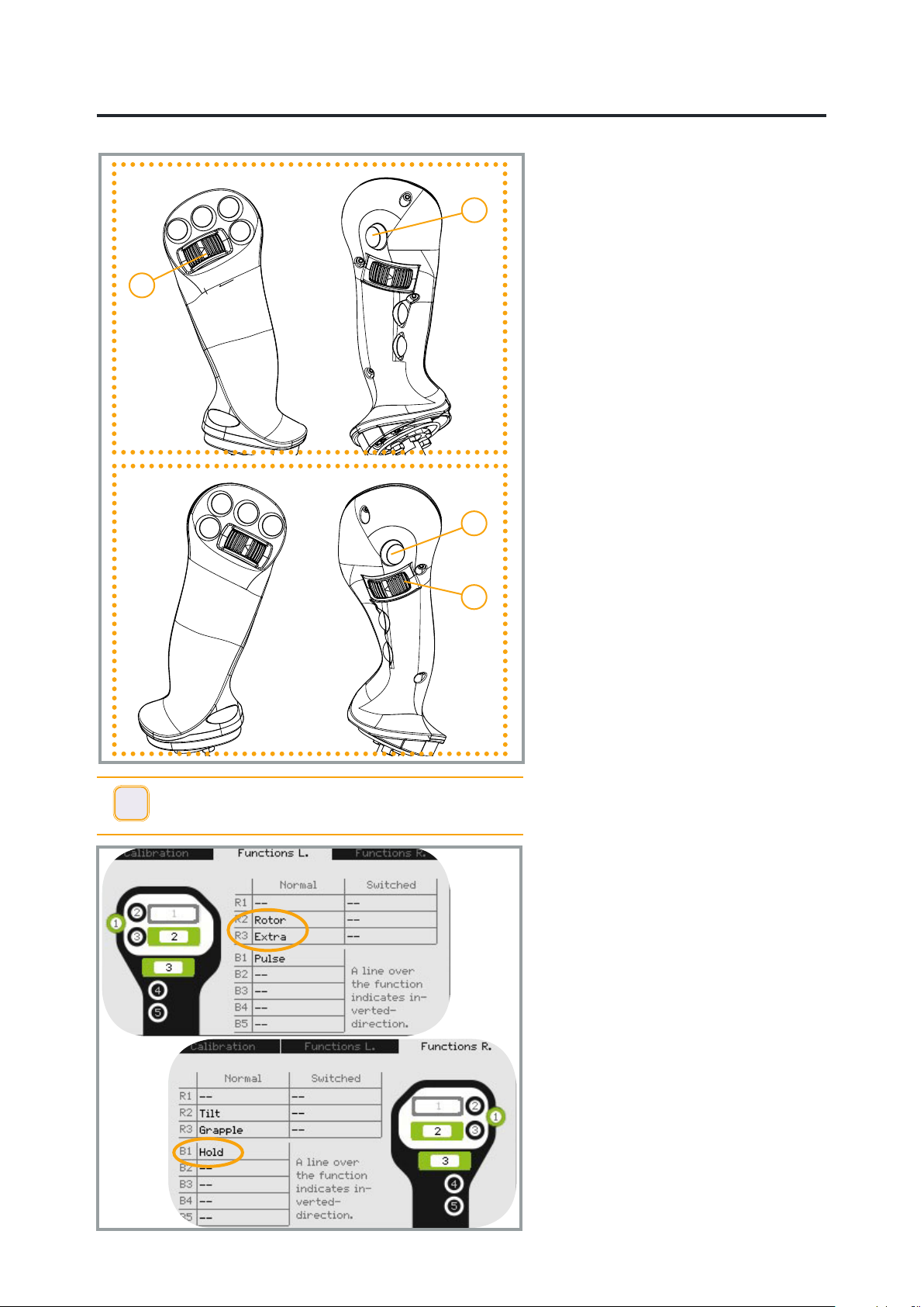
Handle
The handles are equipped with switches
and rollers to control Rototilt® functions
and base machine functions.
The standard version has 2 rollers and 7
switches in each handle.
There are 5 switches for the base
machine functions.
The handle functions are congured by
an authorised installer. Functions are
programmed according to the following
standard unless otherwise stated.
Left Handle
A Rotation
1 Option 1
D Extra 2
Right Handle
B Tilt
2 Option 2
C Extra/Grapple
Also see sticker and display
!
IMPORTANT - The base machine’s factor-installed
handles have been replaced with handles adapted
for ICS.
Carefully check the changed functions, for both the
base machine and Rototilt®.
Machine control
Machine control regulates the oil ow to
the hydraulic circuit for extra equipment
on the base machine. Movement of
the rollers in the handles affects the oil
ow in the machine's main valve via the
control unit.
The system has two different functions:
Rototilt® control
When the 8-pole connector on the stick is
connected, a ow is regulated parallel to
the valves on Rototilt ® and the hydraulic
ow is adjusted to this.
The ow runs in one direction only.
Regulation of extra hydraulics
When the base machine is run without
Rototilt ®, the control can be used to
regulate the oil ow in the machine circuit
for extra hydraulics.
The ow can be regulated in both
directions.
2200397_ _6909

© Rototilt Group AB 2018-03-16
Option 1
Option 2
Track Steering, Turn
Joystick Functions
* Index Finger Side
Activate
Track Steering
Signal horn
Rotation
Pulse function
Shift H.R1 *
X3 *
Track Steering, Operation
Tilt / Swing Boom
Shift X1 /
Swing Boom*
Grapple *
Joystick Functions
* Index Finger Side
Signal horn
Rotation
Pulse function
Shift H.R1 *
X3 *
Tilt / Swing Boom
Shift X1 /
Swing Boom*
Grapple *
5407247 EN
EN English
2200397_ _6909

© Rototilt Group AB 2018-03-16
Planeringsskopa, rotation 360°
Rotation, 360° Rotation, 360°
Planeringsskopa, tilt 40°
Tilt, 40°
Tilt, 40°
Left Handle
1. Rotation, clockwise
2. Rotation, anti-clockwise
Right Handle
3. Tilt, right cylinder extension
4. Tilt, left cylinder extension
4
3
2
1
4
3
2
1
EN English
!
IMPORTANT - When using Rototilt®the base machine/
excavator pedals must not be used to further increase the
oil ow, as this can result in serious damage to Rototilt®.
Operating Rototilt®
The ICS control system permits tilt,
rotation, grapple and an extra function to
be used in parallel and to be regulated
proportionally.
ICS works in parallel with any pedals on
the base machine/excavator. When using
Rototilt® the base machine/excavator’s
pedals must not be used to regulate the
oil ow.
A calibrated ICS system provides each
system with its optimal ow. The Rototilt®
can be seriously damaged if the pedals
on the base machine/excavator are used
to further increase the ow.
Carefully check the positions and
functions of the switches.
The appearance and placement of
switches may vary depending on the
base machine/excavator and handle.
The selected function opens the
equivalent directional valve on Rototilt®.
Activate the ICS control
system
The system is activated when the base
machine/excavator is in the ignition
position.
Speed
The speed of all functions can be
adjusted.
The adjustment is made via Display,
Speed settings menu.
The speed can be adjusted in general
for all functions. The speed can also be
adjusted separately for each individual
function.
Operation
2200397_ _6909
© Rototilt Group AB 2018-03-16
2
Right
Left
B
1
2
D
EN English
Pulsating function
The ICS control system can give a
pulsating, shaking function to spread
material out of a tilting bucket, for
example.
Press switch 1 and regulate the speed
with roller B.
Non-variable hydraulic flow, Extra 2
The ow can be locked using switch 2
(Hold) when the intended level is reached
with roller D (Extra2). Press and hold the
switch for 0.5 seconds.
The next time the switch (2) is pressed
the function releases and the ow
ceases.
!
IMPORTANT -
Carefully check the relevant functions, on the display or
the handle sticker.
2200397_ _6909
© Rototilt Group AB 2018-03-16
EN English
Detach the tool
Position the tool horizontally, resting on
rm ground or so that the tool cannot
slide out of the attachment when the
quick coupler locks are opened.
!
IMPORTANT - If the tool can fall or change position in
connection with the procedure, there is a risk of damaging
the tool and/or quick coupler.
!
IMPORTANT - It is only possible to open the lock when
the start menu is visible or from the troubleshooting menu.
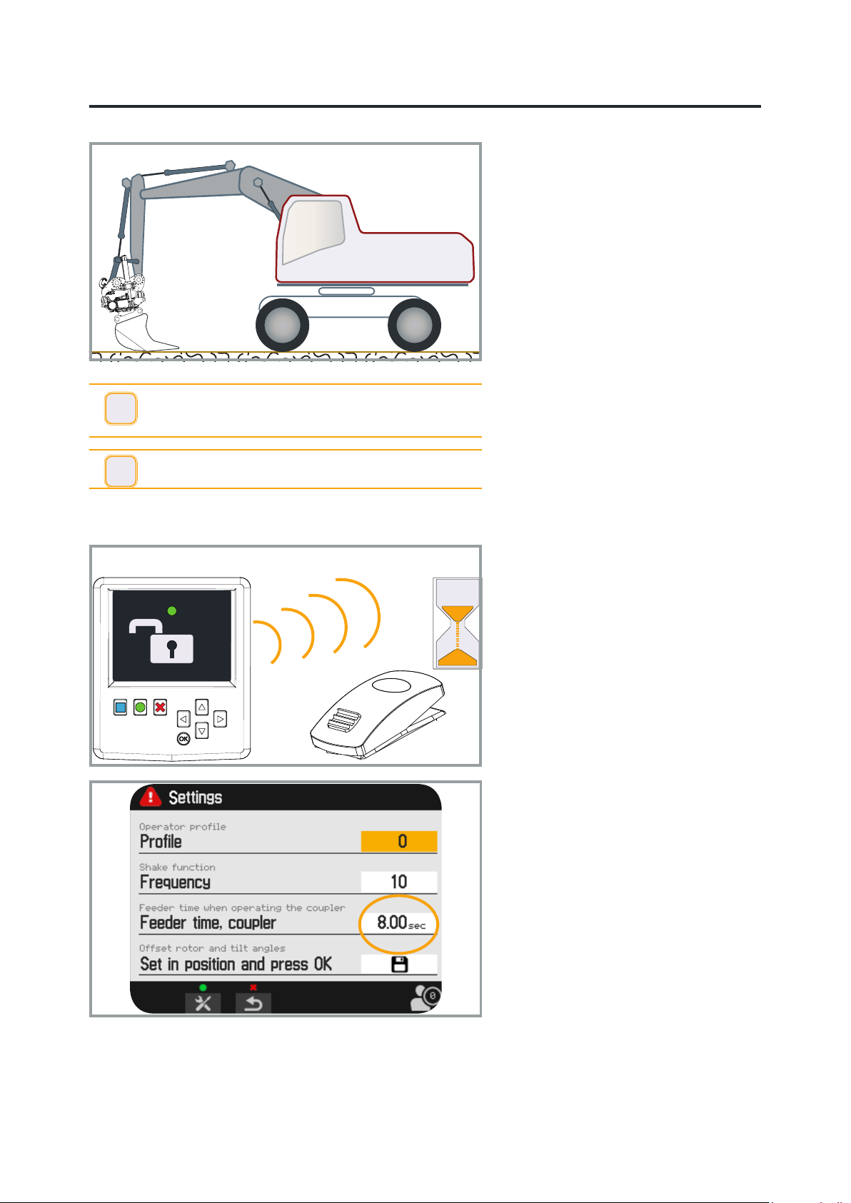
Operating Rototilt® Quick coupler
Check that the display shows the start
menu. The icon for the quick coupler
locking function is shown above the
green function key.
First press the green function key and
release it.
The buzzer sounds.
Now move the quick coupler locking
function switch to the open position.
The switch is enabled for a period of 10
seconds.
The lock remains open as long as the
switch remains open, but pressurising
is only performed during the preset time
period, 3-12 seconds.
The selected time can be checked on the
display, Menu settings.
The switch must be switched on and then
off again to repressurise the hydraulic
cylinder.
See the Instructions for Use for the quick
coupler.
2200397_ _6909
© Rototilt Group AB 2018-03-16
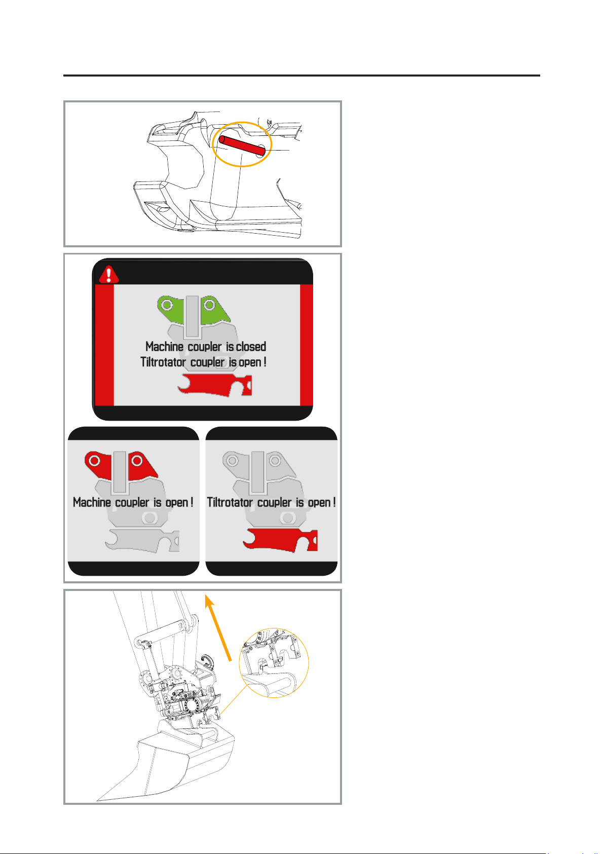
Indicator Rod - Open
EN English
When Rototilt® is pressurised
hydraulically the quick coupler locking
function is opened. The indication on the
quick coupler shows that the lock is open.
When the quick coupler’s locking wedge/
locking bolts are fully open, the tool can
be detached by slowly retracting the
bucket cylinder.
Return the switch to its original position
to close the lock.
Pressurising is conducted for a preset
time, maximum 12 seconds.The selected
time can be checked on the display,
Menu settings.
The switch must be switched on and then
off again to repressurise the hydraulic
cylinder.
A warning is shown on the display if the
quick coupler is in the open position.
The base machine/excavator can be
equipped with different combinations
of quick coupler and machine coupler.
The gure and text on the display are
dependent on the combination.
Both the quick coupler and the machine
coupler are available with and without
electronic monitoring (SecureLock).
2200397_ _6909

© Rototilt Group AB 2018-03-16
Indicator Rod - Closed
Locking Wedge - Closed
EN English
Attach the tool
Open the quick coupler and check that
the indication shows that the coupler is
open.
Refer to the Quick coupler section.
Position the quick coupler so that its
coupling mechanism is correctly aligned
with the tool’s attachment frame.
Now slowly pivot the tool by extending
the bucket cylinder.
Adjust with small stick or boom
movements if necessary.
Return the switch for quick coupler
locking function.
The quick coupler’s locking cylinder
returns to its closed position. The
indication on the display conrms that the
switch is in the locked position.
The indicator on the quick coupler shows
that the quick coupler locking function is
in the locked position.
Inspection of quick coupler locking
function
i
INFO - If the quick coupler locking function is in the
closed position when the attachment is attached, the
switch must be switched on, off and on again.
Inspection of the quick coupler
locking function
Even if the indication shows that the
locking wedge has engaged in the locked
position, perform the following test to
check the tool is attached securely:
Push the tool forwards towards the
ground, see the gure to the left.
Operate the bucket in this position,
inwards and outwards, to check that
the locking wedge has locked the tool
correctly.
Rotate the quick coupler and check from
the operator position that the locking
wedge/locking pistons have engaged.
In the event of uncertainty, exit the
machine and conduct a visual check.
2200397_ _6909
Ce manuel convient aux modèles suivants
1
Table des matières
Autres manuels Volvo Matériel de construction

Volvo
Volvo ECR25 Electric Manuel utilisateur

Volvo
Volvo L30G Manuel utilisateur

Volvo
Volvo Ingersoll Rand SD-116 TF Series Manuel utilisateur

Volvo
Volvo L150H Manuel utilisateur

Volvo
Volvo G700B Series Manuel utilisateur

Volvo
Volvo EC330B Manuel utilisateur

Volvo
Volvo ECR50D Manuel utilisateur

Volvo
Volvo BHL Instructions d'utilisation et d'installation

Volvo
Volvo DD24 Manuel utilisateur

Volvo
Volvo DD29 Manuel utilisateur


