Visual Robotics VIM-303 Manuel utilisateur

VIM-303 User Interface Manual Page 1 5/8/2023
VIM-303
Unboxing and
Hardware Assembly
Manual
For Firmware Release.2.50.492b3d96.202305081306

VIM-303 User Interface Manual Page 2 5/8/2023
Scope and other documentaon
This manual covers how to connect the VIM-303 to a robot. Other relevant manuals include:
•User Interface Manual
•Blockly Programming Manual
•Sengs Manual
•First Picks with VIM-303 Manual
Unboxing VIM-303
The VIM-303 vision guidance system comes packed in a cardboard box (Figure 1). Under the ap is an
informaon label indicang that the assembly instrucons are on the ash drive (Figure 2). The camera
and ash drive with instrucons are underneath the top piece of foam (Figure 3). Keep the cardboard box,
as this will be a useful test object for your rst picking experience (Figure 4). The back of the camera has
the camera’s hostname, published on the network via mDNS, which you will need later.
Figure 1 Figure 2
Figure 3 Figure 4
Figure 5

VIM-303 User Interface Manual Page 3 5/8/2023
Assembling the Gripper Kit and Mount
Figure 6 shows the gripper kit components. Figure 7 shows the Mount and the sucon end eector from
the gripper kit.
Figure 6
Figure 7

VIM-303 User Interface Manual Page 4 5/8/2023
Assemble the sucon end eector to the mount (Figure 8), ensuring that the green exhaust port faces
toward the triangular face of the mount and the gripper is on the side of the mount with the circular ridge
(Figure 9). The mount is fastened with the four included M4 athead screws (Figure 10). Aach the mount
assembly to the wrist of a Universal Robots UR3, UR5, or UR10, ensuring that the exhaust port is aimed in
the same direcon as the wrist connector using the four included M6 screws (Figure 11).
Figure 8 Figure 9
Figure 10 Figure 11

VIM-303 User Interface Manual Page 5 5/8/2023
Assembling the Pneumac Valve
Connect the wires from the valve to DO0 and 0V on the Universal Robots controller. Polarity isn’t crical,
but for convenon hook the black wire to 0V. Cut the black 6mm tubing to length as desired and connect
the air inlet tubing to port P and the controlled air outlet to the gripper to B. Aach the compressor
coupling to the tubing connected to port P (Figure 14) and connect the 6mm to 4mm adapter to the tubing
connected to port B (Figure 15). Connect the 4mm tubing to the gripper (Figure 16).
Figure 12
Figure 13

VIM-303 User Interface Manual Page 6 5/8/2023
Figure 14 Figure 15
Figure 16

VIM-303 User Interface Manual Page 7 5/8/2023
Assembling the Camera to the Mount
Aach the camera onto the mount using the three included M5 screws (Figure 17). Carefully screw on the
Ethernet cable into the camera as shown (Figure 17).
Figure 17
Plugging Everything In
Prepare to plug the VIM-303 cable into a PoE switch, capable of at least 15W. Wait unl the power on step
on the next page. Plug the Universal Robots controller into the switch and power on the robot. Connect
the switch to the network or connect a PC or tablet for isolated operaon (Figure 18).
Figure 18
VIM-303 User Interface Manual Page 8 5/8/2023
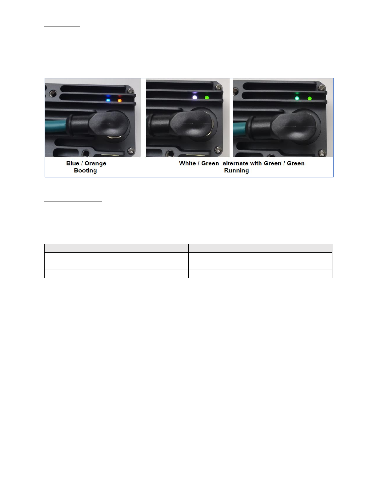
Powering Up
Plug the camera into the PoE switch. Immediately the status lights should show solid blue on the le and
blinking or solid orange on the right, indicang the camera is boong (Figure 19). The orange light is the
Ethernet acvity light, while the blue light is a boot status light. Aer about 45 seconds, the le boot status
light should alternate between white and green about once per second and the right Ethernet acvity light
should blink green if connected to a high speed network or orange otherwise.
Figure 19
Network Connecon
The camera can connect onto the network in several ways. If it is connected to a network supporng DHCP,
it will receive an address. If it is on an isolated network, it also generates a stac address at 192.168.1.47.
The camera broadcasts its hostname over mDNS at the address indicated on the label on the back of the
camera such as vrobocs8771.local (Figure 5). Figure 20 indicates the various network conguraons.
Network Type
IP address
mDNS (stac or DHCP)
vrobocs8771.local (whatever is on nameplate)
DHCP
IP address leased from router
Isolated network
192.168.1.47
Figure 20

VIM-303 User Interface Manual Page 9 5/8/2023
Connect to the Camera
Connect to the camera on hhtp port 8080. Let’s assume the camera is on a DHCP network and is leased an
address of 192.168.0.100 and that its hostname (printed on the nameplate) is vrobocs8771. Here are the
two methods of connecng to the camera (using a browser such as Chrome):
hp://192.168.0.100:8080
vrobocs8771.local:8080
When you have connected to the web page, you will see a screen that looks like this (Figure 21).
Figure 21
Familiarity with the User Interface
You are encouraged to read the User Interface Manual at this point in order to become familiar with
navigang the camera’s web interface. You will need to navigate to the sengs page in the programming
menu in order to connect the camera to the robot.

VIM-303 User Interface Manual Page 10 5/8/2023
Seng Robot’s TCP (Tool Center Posion)
Set the robot’s TCP (using the provided sucon gripper) to Z=205mm with all other osets equal to zero
(Figure 22).
Figure 22
Manuels Matériel réseau populaires d'autres marques

Matrix Switch Corporation
Matrix Switch Corporation MSC-HD161DEL Manuel utilisateur

B&B Electronics
B&B Electronics ZXT9-IO-222R2 Manuel utilisateur

Yudor
Yudor YDS-16 Manuel utilisateur

D-Link
D-Link ShareCenter DNS-320L Manuel utilisateur

Samsung
Samsung ES1642dc Instructions d'utilisation

Honeywell Home
Honeywell Home LTEM-PV Instructions de montage


