Viso Systems LabRail Manuel utilisateur

VISO SYSTEMS LabRail
User Manual
Revision: 17DEC2021

2
Congratulations on purchasing your new Viso Systems LabRail. Before using this
product, please read the Safety Information.
This manual contains descriptions and troubleshooting necessary to install and
operate your new Viso Systems product. Please review this manual thoroughly to
ensure proper installation and operation.
For news, Q&A and support at Viso Systems, visit our website at
www.visosystems.com

3
Contents
Safety Information........................................................................................................4
Disposing of this Product ..............................................................................................4
Introduction..................................................................................................................4
Shipping Dimensions.....................................................................................................5
LabRail installation........................................................................................................5
Power and data connection........................................................................................14
Distance calibration ....................................................................................................17
Sensor Distance...........................................................................................................24
Specifications..............................................................................................................25

4
Safety Information
Warning! This product is not for household use.
Read this manual before installing and operating the LabRail, follow the safety
warnings listed below, and study all the cautions in the manual.
Preventing electric shocks
Make sure the power supply is always grounded.
Use a source of AC power that complies with the local building and electrical codes,
that has both overload and ground-fault protection.
If the controller or the power supply are in any way damaged, defective, wet, or
show signs of overheating, disconnect the power supply from the AC power and
contact Viso Service for assistance.
Do not install or use the device outdoors. Do not spray with or immerse in water or
any other liquid.
Do not remove any covers or attempt to repair the controller or the power supply.
Refer any service to Viso.
Disposing of this Product
Viso Systems products are supplied in compliance with Directive 2012/19/EU on
waste - electrical and electronic equipment (WEEE) together with the RoHS Directive
2011/65/EU with amendments 2015/863. Help preserve the environment! Ensure
that this product is recycled at the end of its lifetime. Your supplier can give details of
local arrangements for the disposal of Viso Systems products.
Introduction
About this document
These guidelines describe the installation process of the LabRail and distance
calibratio procedure.
About the LabRail
The LabRail is a revolutionary new automatic sensor positioning system, which
includes fully motorized sensor positioning include data over power elliminating all
cables.
© 2007 Viso Systems ApS, Denmark
All rights reserved. No part of this manual may be reproduced, in any form or by any means,
without permission in writing from Viso Systems ApS, Denmark. Information subject to change
without notice. Viso Systems ApS and all affiliated companies disclaim liability for any injury,
damage, direct or indirect loss, consequential or economic loss or any other loss occasioned by
the use of, inability to use or reliance on the information contained in this manual.

5
Shipping Dimensions
Box 1: 1050 x 350 x 200 mm (weight: coming soon)
Box 2: 330 x 220 x 150 mm (weight: coming soon)
Box 3: 780 x 380 x 240 (weight: coming soon)
Box 4: 1650 x 280 x 280 mm (weight: coming soon)
LabRail installation
Suspension principle
The standard rail consists of eight 1.5-m rail pieces. Not all pieces need to be
installed for the system to work –just choose your own preferred length. The rail can
also be prolonged with more rail pieces from Viso Systems.
Gravity and symmetry holds the assembly in place.
Hence it is important that eyebolts in your ceiling are firmly attached to the building
structure (not to suspended ceiling parts or the like). It is also important that the
suspension wires are symmetrical around the rail. This is to avoid skewing of the rail
and to secure balance. The rail suspension is very flexible when it comes to ceiling
heights. The suspension wires can be as long or as short as desired.
The rail is intended to be assembled as a whole on the floor. When this is completed,
wires are attached. The whole rail is lifted manually (about 5 people needed) to its
permanent position and wires are tightened and cut to length.
The dolly, end stop, injector, monopod and cables are installed. Your LabSensor fits
directly onto the monopod.

6
Finally, you need to go through a distance calibration procedure.
Standard pliers and a screwing machine with allen key bits are the tools needed.
LabRail Components
The standard rail consists of 8 rail sections each being 1.5 m long. The rail sections
are interconnected using suspension plates on top and bottom.
The LabRail suspension contains:
Qty
Rail parts
Image
8
1.5-m pieces of aluminium
rail
40
Connector Profiles
9
Suspension plates
80
Screw M5x6
20
M6x30 Ring Screw
34
Conductor Rail
40
Safety wire hooks (push-
through)
100
m
Steel Wire 1.5mm Black (2
rolls, each 50 m)
70
Grub Screw M5x6
1
Wire cutter
Qty
System parts
Image
1
Dolly
1
End Stop

7
Qty
System parts
Image
1
Injector
1
Cable IEC 5m Extension
1
Cable Power 2m
1
Cable RJ45 3m
1
Telescopic arm (monopod)
A48
The whole rail is assembled on the floor. The 1.5-m pieces are attached to one
another with suspension plates for firm alignment and electrical connection.
1. Align the aluminium rail pieces on the floor. Put the rail piece with the end
stop closest to the goniometer. Put the rail piece with the injector module
farthest away from the goniometer.
2. Push the connector profiles into the grooves in the rail –4 at each of each
rail pieces: 2 on the top and two in the bottom grooves.
3. Start by joining the rail pieces on the bottom side of the rail: Use the grub
screws M5x6 to fasten the connector profiles into the rail grooves.
Push the rail pieces tightly together.
4. Turn the rail up-side-up.
5. On the top side: Use the M5x6 screws to the suspension plates to the
rail pieces –2 screws into every connector profile.
8
Important: Please check that rail pieces are indeed accurately
aligned by running your finger across the assembly lines. If needed,
loosen the screws and re-align. Even small misalignments may
prevent the dolly from travelling accurately mechanically.
6. Remove the end stop cover and attach the end stop to the rail with
8 grub screw and 4 connector profiles inside the upper and lower
grooves. Note: The end stop should have the spring load part facing
downward
7. Turn the rail up-side-up.
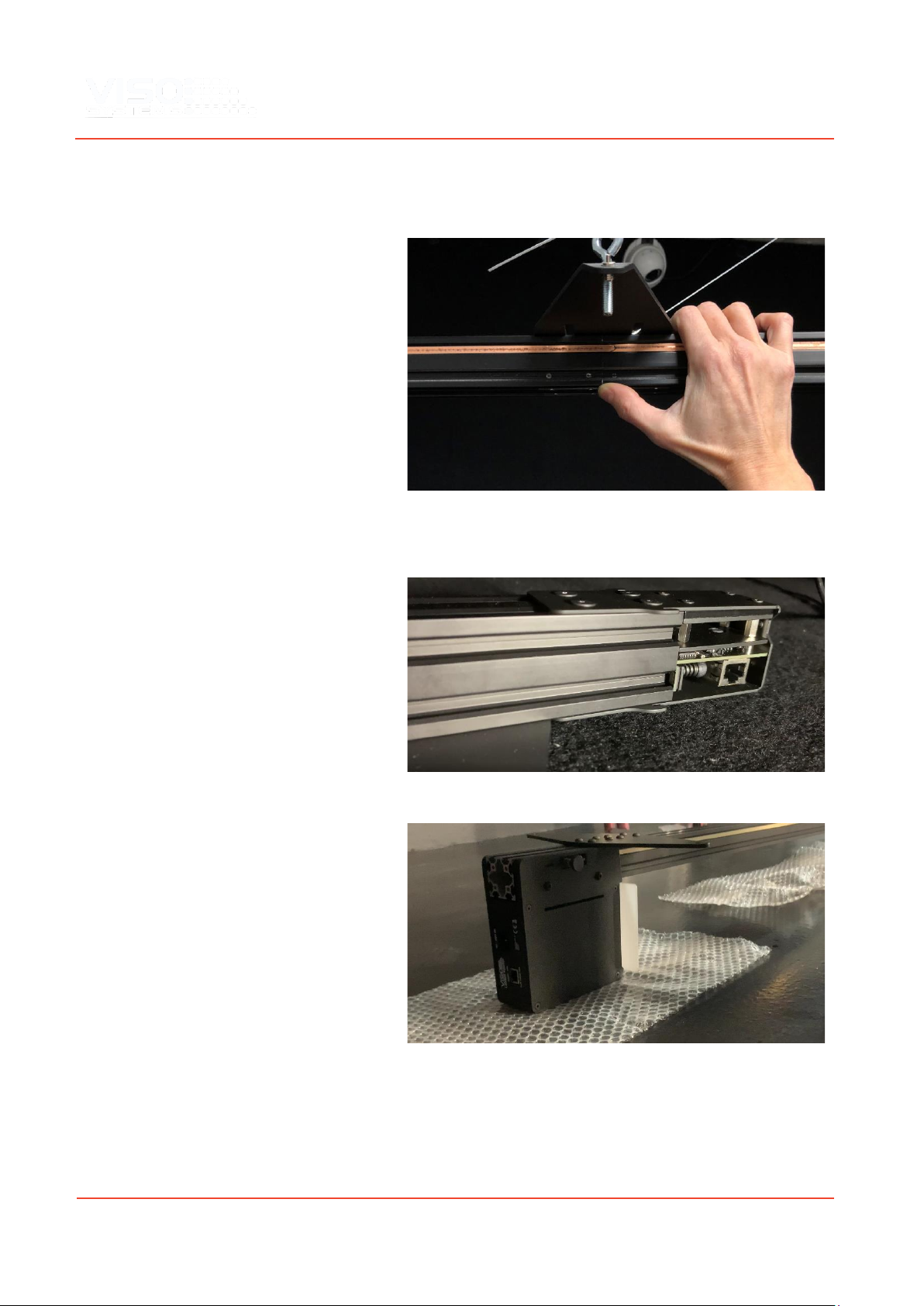
8. Go to the injector unit on the rail end farthest from the goniometer
9. Push the rail conductor pieces into the top groove in both sides of
the rail. Fill each groove.
9
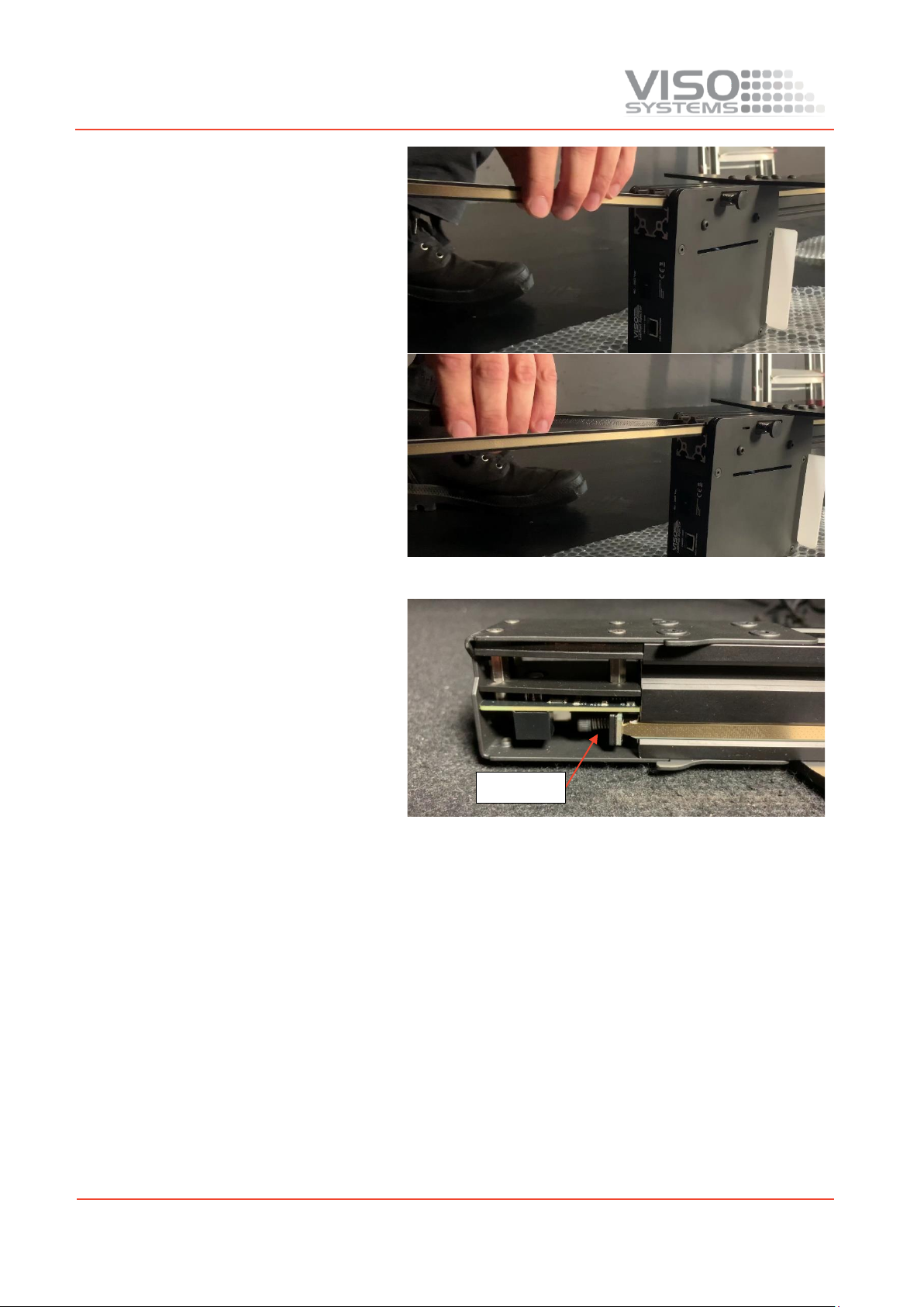
Push all pieces in and check that the first piece meets the spring
load in the end stop:
Also check that the rail conductor pieces all slide freely and that to
can activate the spring load by pushing that all conductor pieces
from the opposite end of the rail.
Spring load

10
10. The last conductor pieces will be too long. Cut the last conductor
pieces to length + 5-10 cm with standard pliers:
11. Then push both conductor line firmly in (thus activating the spring
load at the other end) and tighten the finger screws on each side of
the injector. Use e.g., a ruler in between your hand and the
conductor to make it more comfortable to apply sufficient
pressure.
12. Cut the remaining conductor pieces off if needed.
13. Screw two eye bolts into every suspension plate (for wire
attachment)
14. Please firmly attach your own eyebolts or the like to the building structure.
The suspension hooks in LabRail kit accommodates can open and close
around up 5.5 mm. Important: Each building eyebolt carries two wires and
should be placed between two rail connectors (except maybe the last set).
As gravity and symmetry holds the construction in place, wires should be
angled vertically about 30-60 degrees to the ceiling to improve stability.
Autres manuels pour LabRail
1
Table des matières
Autres manuels Viso Systems Équipement de laboratoire


Manuels Équipement de laboratoire populaires d'autres marques


Agilent Technologies
Agilent Technologies 5800 ICP-OES Manuel utilisateur

Endress+Hauser
Endress+Hauser Cleanfit CPA875 Manuel utilisateur

NI
NI PXI-5422 Manuel

Collomix
Collomix Aqix Manuel utilisateur

SPEX SamplePrep
SPEX SamplePrep 6875 Freezer/Mill Series Manuel utilisateur

Ocean Insight
Ocean Insight FLAME-NIR+ Manuel utilisateur


