Virtualfly SOLO GA1 Manuel utilisateur

© 2022 Virtual Fly, SL
All trademarks and brand names are
trademarks or registered trademarks of their
respective owners. All rights reserved.
C. Maria Aurèlia Capmany, 21
P.I. La Fàbrica – 08297 Castellgalí (Spain)
Phone: (+34) 938 333 301
https://www.virtual-fly.com
For support, contact us at
support@virtual-fly.com
SOLO GA1
USER’S MANUAL
Rev. 2.0 - April 2022

SOLO GA1 | User’s manual
2
TABLE OF CONTENTS
1. IN THE BOX..........................................................................3
2. HARDWARE SETUP
. CONNECTING TO PC.............................................
. ADJUSTING MAGNETIC LABELS
ACCCORDING TO AIRCRAFT TYPE...........................
. G BACKLIGHT CONTROLS..........................
. G OSD CONTROLS........................................
. SOLO GA NAKED EDITION.................................
3. SOFTWARE SETUP
. CONFIGURING PFD/MFD DISPLAYS IN
WINDOWS........................................................................
. INTERFACE WITH FLIGHT SIMULATION
SOFTWARE AND PC...................................................
. CONFIGURING G SCREENS INSIDE
SIMULATION SOFTWARE...........................................
4. ENGINE STARTING PROCEDURES
4.1 START & STOP PISTON ENGINES......................14
4.2 START & STOP TURBOPROP ENGINES................16
5. TROUBLESHOOTING........................................................18
6. REMOTE SUPPORT...........................................................19
7. TECHNICAL SPECIFICATIONS........................................20
8. AIRCRAFT COMPATIBILITY..............................................21

B
E F
I
H
G
JK1x
SOLO GA1 | User’s manual 3
1. IN THE BOX
A) SOLO GA panel
B) USB Hub ports
C) USB Cable (x in "Naked Edition")
D) Power supply v (Not included in "Naked
Edition")
E) Power strip
F) HDMI cables (Not included in "Naked Edition")
G) Magnetic Labels
H) Spiral cable wrap
I) Cable ties
J) Quick Start Guide
K) Registration Key
A
C
1x
1x 4x 1x
1x 2x
10x
1x
1x
1x
C
D

SOLO GA1 | User’s manual
4
2. HARDWARE SETUP
2.1 CONNECTING TO PC
The SOLO GA has been developed to be pluggable to any
standard Windows computer that has two free video outputs
and one free USB port.
Most of the connections of your SOLO GA will come assembled
so you have to connect the least amount of cables. Connect
the HDMI (F) and USB Hub (B) to your PC, and the power supply
to a wall socket. Follow the complete connections schematic
displayed in the next diagram. Use the spiral cable wrap (H) to
tie and organise the cables.
Flight Simulator
computer
USB (C) USB (C) USB (C)
USB
Swit-
ches
Power
supply v
(D)
Power supply v (D)
HDMI (F)
HDMI (F)
USB Hub
USB
Hub
Power
USB Hub (B)
Flood
light
Power Strip (E)

SOLO GA1 | User’s manual 5
2.2 ADJUSTING MAGNETIC LABELS
ACCORDING TO AIRCRAFT TYPE
The SOLO GA1 is a multifuncion panel and some switches
change their function depending on whether the selected
aircraft is a piston, turbo-prop. or jet. The panel incorporates
some magnetic labels, shown below, which allow you to
change the designation of each switch and rotary switch to
match the correct functionality. The default designation of
the switches and rotaries (without the magnetic labels) is for
piston engine aircraft.
To apply the magnetic labels, simply place them over the
SOLO GA panel in their correct location, as displayed in
the image below. The image depicts the SOLO GA with the
turboprop magnetic labels applied.

SOLO GA1 | User’s manual
6
2.3 G1000 BACKLIGHTING CONTROL
You can control the backlighting of the PFD, MFD and Audio
panels from the equipment itself.
• Double tap the “VOL PUSH ID” (a) to turn ON/OFF the
backlighting of PFD/MFD panels.
• Rotate whilst you press the “VOL PUSH ID” (b) to adjust
the backlighting of PFD/MFD panels.
• Double tap the “PILOT PASS” (c) to turn ON/OFF the
backlighting of the Audio panel.
• Rotate whilst you press the “PILOT PASS” (d) to adjust the
backlighting of the Audio panel.
a
b
c
d
2.4 G1000 OSD CONTROLS
The screens come configured from factory, but the user
can access the screen menus using the rotary switches and
buttons displayed below.
e
f
g
• MENU: push “VOL SQ” (e) + move the “JOYSTICK RANGE”
(f) right
• DOWN: push “VOL SQ” (e) + move JOYSTICK “RANGE”
(f) down.
• EXIT: push “VOL SQ” (e) + move JOYSTICK “RANGE” (f)
left.
• POWER: push “VOL SQ” (e) + push “ENT” (g).

SOLO GA1 | User’s manual 7
2.5 SOLO GA1 NAKED EDITION
If you have purchased the SOLO GA1 "Naked" Edition, you
have received everything described in Section 1 except the
VF-G1000's PFD, MFD and Audio panels.
Use the following accessories from the VF-G1000 package to
mount the VF-G1000 in the SOLO GA1 Naked:
C) Power Supply G) HDMI cables (x)
D) EU Power cable H) USB cable (x)
E) US Power cable I) Mx Countersunk screws
(x) and "U" shaped support
with spacers and butterfly
screws (x).
F) Jack cables (x2)
The Audio panel must always be mounted using the provided
“U”-shaped support and butterfly screws. Use the appropriate
number of spacers to ensure adequate tightening.
Once fixed, bend the “U”-shaped supports, as
displayed in the following diagram, to get the best
results.
Mount the PFD/MFD panels to the SOLO GA1 Naked from the
front with the provided countersunk screws (I) from the VF-
G1000 package, as displayed in the diagram below.

SOLO GA1 | User’s manual
8
After mounting the PFD, MFD and Audio panels, you must
connect these to the SOLO GA Naked and flight simulation
PC. The cables described below are provided with the VF-
G package. You must connect:
• The jack cables (F) from the Audio panel to PFD and MFD
panels, as displayed in the following diagram.
• USB cables (H) from PFD, MFD and Audio Panel to SOLO
GA's USB Hub.
• HDMI cables (G) from PFD and MFD to flight simulation
PC.
• Power supply (C) from PFD to Power strip (E).
The schematics of the USB, HDMI and Power supply
connections are displayed in the diagram from Section ..
PFD - MFD 12vdc IN
VGAHDMIUSB
12vdc OUT PFD - MFD 12vdc IN
VGAHDMIUSB
12vdc OUT
12vdc IN
12vdc OUT
USB
Jack
Cable (F)
Jack
Cable (F)

SOLO GA1 | User’s manual 9
3. SOFTWARE SETUP
3.1 CONFIGURING PFD/MFD DISPLAYS IN
WINDOWS
SOLO GA panel includes a VF-G system with a Primary
flight display (PFD), Audio Panel and Multi flight display (MFD).
Before configuring the screens:
. Check the selector mode switch at the back of PFD
and MFD displays that is properly set according to the
position of PFD/MFD in cockpit.
One scenery
display
Multiple scenery
displays
PFD - MFD PFD - MFD1 2vdc IN
VGAHDMIUSB
12vdc OUT
The 12VDC power supply must be disconnected for
the change to be applied. Otherwise, the device will
remain in the previous state.
. Turn on the flight simulation computer.
Open “Display Settings” and make sure that the “Display
resolution” of both displays is set to 1024x768, as displayed
below. We recommend to set up the MFD on the right-hand-
side of the PFD panel. On “Display Settings”, the PFD and
MFD displays must be positioned under the main display, as
depicted below.
If you have multiple scenenery displays,you must
set the leftmost scenery display as Main display.

SOLO GA1 | User’s manual
10
3.2 INTERFACE WITH FLIGHT SIMULATION
SOFTWARE AND PC
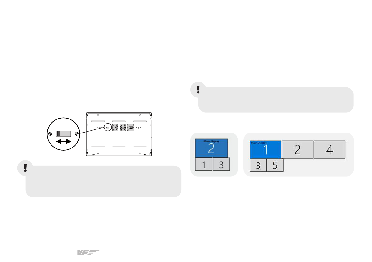
SOLO GA1 SWITCHES AND BUTTONS
The SOLO GA1 interacts with any computer using our own
custom protocol through VFHub, which makes it compatible
with MSFS and X-Plane 11. VFHub is the software developed
by Virtual Fly to simplify setting up our products. With VFHub,
you can fly your favorite flight simulation software without
worrying about configuring your Virtual Fly flight controls.
You can download the latest VFHub version from this link:
https://www.virtual-fly.com/setup-support. The VFHub installer
takes care of installing VFHub and all the required modules.
VFHub is compatible with MSFS, Prepar3DV4-V5 and X-Plane 11,
but Prepar3D is not available for the SOLO GA1.
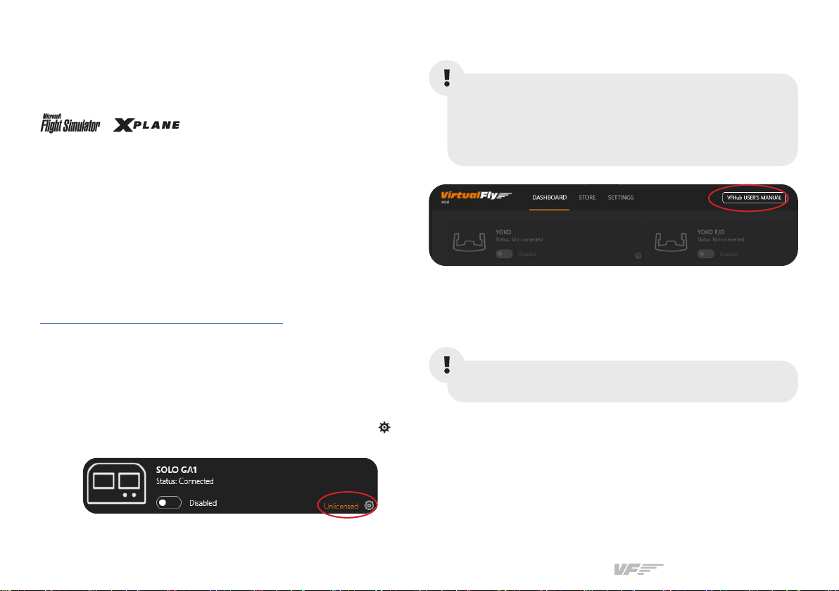
After installing VFHub, make sure your SOLO GA1 is connected
to your computer. Run VFHub, locate the SOLO GA1 section in
the Dashboard and select the device's options button ( ).to
access the SOLO GA1 settings screen,
VFHub takes care of making your SOLO GA1 work with MSFS
and X-Plane 11, so it must always be running when you use
the SOLO GA1.
VF-G1000
The PFD, MFD and Audio panels of the SOLO GA1 interact
with any computer both as a joystick (HID) and with our own
custom protocol. This makes it compatible with any flight
simulation software. However, we recommend configuring it
through VFHub, and only oer support to set it up using this
method.
Inside the SOLO GA1 settings screen, you will need to
input the provided registration key (K) and select the COM
port to activate your SOLO GA1. For detailed instructions
on getting your device running, check the USER’s
MANUAL button in the VFHub software.
Check out the table from section 8 to see which aircraft
you can fly using the SOLO GA1.
Table des matières
Autres manuels Virtualfly Changer


