Viptela vEdge 100b Manuel technique

Planning and nstallation
This article provides general safety standards to adhere to when installing or connecting a vEdge 100b router or its
components.
General Safety Standards
• nstall your vEdge router in compliance with the following local, national, and international electrical codes:
◦ United States—National Fire Protection Association (NFPA 70), United States National Electrical Code.
◦ Other countries— nternational Electromechanical Commission ( EC) 60364, Part 1 through Part 7.
◦ Evaluated to the TN power system.
◦ Canada—Canadian Electrical Code, Part 1, CSA C22.1.
• Locate the emergency power-off switch in the room in which you are working. n case of an electrical accident, quickly
turn off the power.
• Disconnect power before installing or removing the router.
• f an electrical accident occurs, use caution and immediately turn off power to the router.
• Make sure that grounding surfaces are thoroughly cleaned and well-finished before grounding connections are made.
• Do not work alone if hazardous conditions exist.
• Always check that power is disconnected from a circuit. Never assume that it is disconnected.
• Carefully inspect your work area for possible hazards, such as moist floors, worn-out power cords, ungrounded power
extension cords, and missing safety grounds.
• Operate the device within marked electrical ratings and product usage instructions.
• To ensure that the router and the FRUs function safely and correctly, use the specified cables and connectors, and
make certain they are in good condition.
Additional nformation
Prepare for Router nstallation
nstall the vEdge 100b Router
Connect the vEdge 100b Router
vEdge Router Default Configuration
https://docs.viptela.com/02vEdge_Hardware/02vEdge_100b_Router/03Planning_and_ nstallation
Created on: Mon, 25 Jan 2016 18:36:33 GMT
Generated by: [email protected]
1

Prepare for Router nstallation
This articles provide guidelines and requirements for preparing your site to install the vEdge 100b router.
Site Preparation Guidelines
Efficient operation of your vEdge 100b router requires proper site planning and proper layout of your equipment rack or
wiring closet:
• Ensure that the area around the router is kept free of dust and conductive material.
• Follow appropriate airflow guidelines so that the cooling system functions normally.
• Follow ESD prevention procedures to avoid any damage to the router.
• nstall the router in an enclosed, secure area allowing only authorized personnel to access the device.
Environmental Requirements
nstall the vEdge 100b router in a dry, clean, temperature-controlled, and well-ventilated environment:
• Maintain ambient airflow for the router to operate normally. The ambient intake air temperature should be in the range
0°C to 40°C (32°F to 104°F). f the airflow is blocked or if the air intake is too warm, the router can get overheated.
• Avoid temperature extremes. Ensure that the router is operating at an ambient temperature not more that 40°C (104°F)
at sea level. For higher altitudes, a derating of 1.50°C per 1,000 feet applies.
• High humidity conditions can cause moisture to penetrate into the chassis. The device supports 10% to 85% humidity
levels, non-condensing.
Rack Requirements
You can mount the vEdge 100b router in a two-post or a four-post rack. Table 1 provides the rack requirements for the
router.
Table 1: Rack Requirements for vEdge 100b Routers
Rack Requirement Guidelines
Rack type
Use a two-post or a four-post rack that meets the size requirements for the router, provides
bracket holes or hole patterns spaced at 1 U (1.75 in. or 4.45 cm) increments, and is strong
enough to support the weight of the router.
https://docs.viptela.com/02vEdge_Hardware/02vEdge_100b_Router/03Planning_and_ nstallation/01Prepare_for_Router_ nstallation
Created on: Mon, 25 Jan 2016 18:36:33 GMT
Generated by: [email protected]
2

Rack Requirement Guidelines
Mounting brackets Ensure that the holes in the mounting brackets are spaced at 1 U (1.75 in. or 4.45 cm). This
allows you to mount the router in any location in the rack.
Rack size
t is recommended that the rack comply with the size and strength standards of a 19-inch rack
as defined in Cabinets, Racks, Panels, and Associated Equipment (document number
E A-310–D), published by the Electronics ndustry Association http://www.eia.org. Ensure that
the rack rails are spaced widely enough to accommodate the external dimensions of the
chassis and that the outer edges of the front mount brackets extend the width of the chassis to
19 in. (48.2 cm). You must also ensure that the spacing of rails and adjacent racks allows for
the proper clearance around the router and rack.
Rack secured to
building structure For maximum stability, secure the rack to ceiling brackets and to floor brackets.
Additional nformation
nstall the vEdge 100b Router
https://docs.viptela.com/02vEdge_Hardware/02vEdge_100b_Router/03Planning_and_ nstallation/01Prepare_for_Router_ nstallation
Created on: Mon, 25 Jan 2016 18:36:33 GMT
Generated by: [email protected]
3

nstall the vEdge 100b Router
Once you have prepared your site for router installation, unpack the vEdge 100b router and mount it either on the wall
or in a 19-inch rack.
Unpack the vEdge 100b Router
A vEdge 100b router is shipped in a cardboard carton and secured firmly in place with foam packing material. The
carton contains a packing list and Quick Start instructions. t is recommended that you do not unpack the router till you
are ready to install it.
To unpack the router:
1. Open the top flaps of the carton.
2. Gradually remove the packing foam holding the router and the accessories in place. See Figure 1.
3. Take out the router and each accessory.
4. Verify the router components against the packing list included in the box (see packing list below).
Figure 1: Unpacking the vEdge 100b Router
https://docs.viptela.com/02vEdge_Hardware/02vEdge_100b_Router/03Planning_and_ nstallation/02 nstall_the_vEdge_100b_Router
Created on: Mon, 25 Jan 2016 18:36:33 GMT
Generated by: [email protected]
4

Note: t is recommended that you do not discard the shipping carton and packing material when you unpack the router.
Flatten and store the box in case you need to move or return the router in the future. See Return Hardware.
Packing List for a vEdge 100b Router
The cardboard carton in which the router is packed includes a packing list. Check the parts you receive with your router
against the items on the packing list. The packing list specifies the part number, name, and quantity of each item in the
carton.
f any part on the packing list is missing, contact your customer service representative or contact Viptela customer
support from within the U.S. or Canada by telephone at 800-525-5033 or by email to [email protected].
Table 1 lists the parts shipped with the vEdge 100b router and their quantities.
Table 1: Inventory of Parts Provided with a vEdge 100b Router
Component Quantity
Router chassis 1
USB console cable 1
https://docs.viptela.com/02vEdge_Hardware/02vEdge_100b_Router/03Planning_and_ nstallation/02 nstall_the_vEdge_100b_Router
Created on: Mon, 25 Jan 2016 18:36:33 GMT
Generated by: [email protected]
5
Component Quantity
Mounting ears, left and right 2
Mounting-ear screws (Packet A) 6
Rack-mount screws (Packet B) 4
AC power adapter (with connector appropriate for your geographical location) 1
Quick Start document 1
Mount the vEdge 100b Router
You can mount the vEdge 100b router in one of the following ways:
• Mount the router in a 19-inch rack
• Mount the router on the wall
n addition to the accessory box, you need the following tools to mount a vEdge 100b router:
• Number 2 Phillips (+) screwdriver
• Tape measure or level
Mount the vEdge 100b Router in a Rack
You can mount the vEdge 100b router on two front posts in a 19-inch rack using simple rack mount ear accessories. To
do so:
1. Place the router chassis on the floor or on a sturdy table near the rack.
2. Verify the internal dimensions of the rack with a tape measure. The rack-mount tray is 440 mm wide and must fit
within the mounting posts.
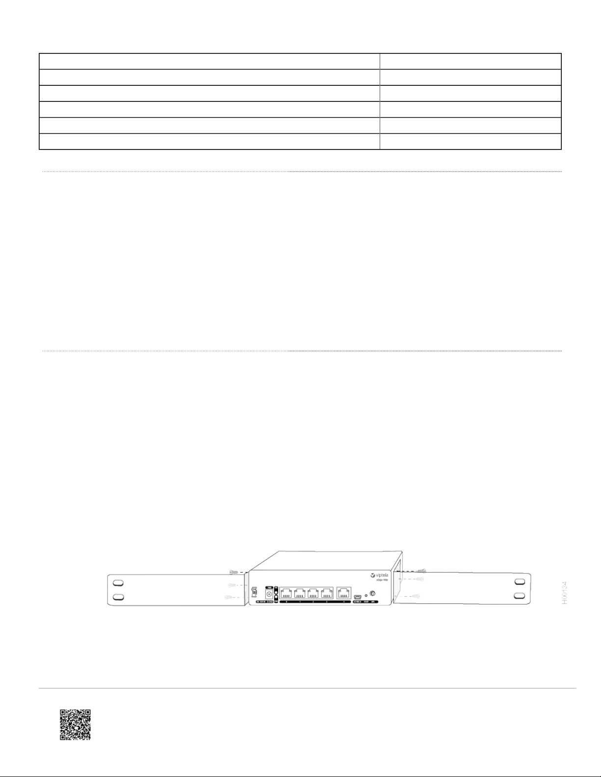
3. Secure the left and right mounting ears to either side of the router chassis using the six screws (two on each side) in
the packet marked A.
Figure 2: Attaching the Mounting Ears to the vEdge 100b Router Chassis
4. Grasp both sides of the router, then lift and position it in the rack, making sure that the mounting ear holes are aligned
with the threaded holes in the rack rail.
https://docs.viptela.com/02vEdge_Hardware/02vEdge_100b_Router/03Planning_and_ nstallation/02 nstall_the_vEdge_100b_Router
Created on: Mon, 25 Jan 2016 18:36:33 GMT
Generated by: [email protected]
6
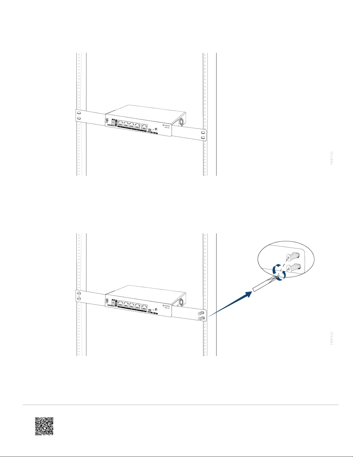
Figure 3: Positioning the vEdge 100b Router in the Rack
5. Secure the mounting ears to the two front posts of the rack using the four rack-mount screws (two on each side) in the
packet marked B. Tighten the screws.
Figure 4: Attaching the Mounting Ears to the Rack
6. Use a tape measure or level to verify that the tray is installed straight and the holes at either ends of the rack align
properly.
Tip: t is recommended that you retain the dust covers on any unused ports.
https://docs.viptela.com/02vEdge_Hardware/02vEdge_100b_Router/03Planning_and_ nstallation/02 nstall_the_vEdge_100b_Router
Created on: Mon, 25 Jan 2016 18:36:33 GMT
Generated by: [email protected]
7

Mount the vEdge 100b Router on the Wall
You can mount the vEdge 100b router on the wall either horizontally or vertically.
To mount the vEdge 100b router on the wall:
1. Measure the distance between the two wall-mount holes on the underside of the router chassis as shown in Figure 5.
Figure 5: Measuring the Distance Between the Wall-Mount Holes
2. nsert two wall-mount screws in the wall where you are mounting the router (screws not provided). The screws must
align with the wall-mount holes on the router's underside.
3. Align the wall-mount holes on the router's underside to the screws in the wall, and gently slide the chassis, from side
to side or up and down, onto the wall-mount screws.
Figure 6: Sliding the Router Chassis onto the Wall-Mount Screws
Additional nformation
Connect the vEdge 100b Router
https://docs.viptela.com/02vEdge_Hardware/02vEdge_100b_Router/03Planning_and_ nstallation/02 nstall_the_vEdge_100b_Router
Created on: Mon, 25 Jan 2016 18:36:33 GMT
Generated by: [email protected]
8

Connect the vEdge 100b Router
This articles describes how to connect the vEdge 100b router to an AC power source and to a management console.
Connect AC Power to the Router
To connect the vEdge 100 router to an AC power source, plug one end of the AC power adapter into the front of the
router, and plug the other end into an AC power outlet as shown in Figure 1.
Figure 1: Connecting AC Power Supply to a vEdge 100b Router
Note: t is strongly recommended that you use the power adapter supplied with the vEdge 100b router.
Connect the Router to LAN and WAN nterfaces
To connect the vEdge 100b router to the LAN, plug the appropriate cable into any port, except port 4, on the front of the
router.
To connect the vEdge 100b router to a WAN, plug the appropriate cable into port 4 on the front of the router.
Connect the Router to a Management Console
To connect the vEdge 100b router to a management console:
1. Connect one end of the USB Type-A to Mini-B connector cable into the console port, labeled CONSOLE, on the
vEdge router (see Figure 2).
2. Connect the other end of the console cable into the console server or to a management console.
https://docs.viptela.com/02vEdge_Hardware/02vEdge_100b_Router/03Planning_and_ nstallation/03Connect_the_vEdge_100b_Router
Created on: Mon, 25 Jan 2016 18:36:33 GMT
Generated by: [email protected]
9

Figure 2: Connecting a vEdge 100b Router to a Management Console
Additional nformation
Log nto a Viptela Device
vEdge Router Default Configuration
https://docs.viptela.com/02vEdge_Hardware/02vEdge_100b_Router/03Planning_and_ nstallation/03Connect_the_vEdge_100b_Router
Created on: Mon, 25 Jan 2016 18:36:33 GMT
Generated by: [email protected]
10
Autres manuels pour vEdge 100b
1
Table des matières
Autres manuels Viptela Routeur réseau


Manuels Routeur réseau populaires d'autres marques


NETGEAR
NETGEAR FS526T - Switch Manuel utilisateur

Korenix
Korenix JetNet 5710G Series Manuel utilisateur

Automated Logic
Automated Logic ZN551 Manuel du propriétaire

Cisco
Cisco ASR 1000 Series Manuel de l'opérateur

EnGenius
EnGenius ESR-9710 Manuel utilisateur

Cisco
Cisco 805 Series Instructions d'utilisation et de sécurité