VeEX AT1702 Manuel utilisateur

Page 1 of 22 AT1700 series Manual D07-00-066P Rev. A00
USER MANUAL
Please direct all questions to your local VeEX Sales Ofce, Representative, or Distributor. Or, contact VeEX technical support at
www.veexinc.com. Copyright 2014 VeEX Incorporated. All rights reserved.
No part of this user manual may be reproduced, translated into a foreign language, or be transmitted electronically without prior
agreement and written consent of VeEX Incorporated as governed by International copyright laws. Information contained in this
manual is provided “as is” and is subject to change without notice. Trademarks of VeEX Incorporated have been identied where
applicable, however the absence of such identication does not affect the legal status of any trademark.
AT1700 Series
Broadband Switches / Multiplexers

Table of Contents
1 GENERAL INFORMATION ..........................................................................4
1.1 Overview .........................................................................................................................4
1.2 Disclaimer .......................................................................................................................4
2 GETTING STARTED ....................................................................................5
2.1 Product Overview ......................................................................................................... 5
2.2 Front Panel ....................................................................................................................6
2.3 Rear Panel ....................................................................................................................6
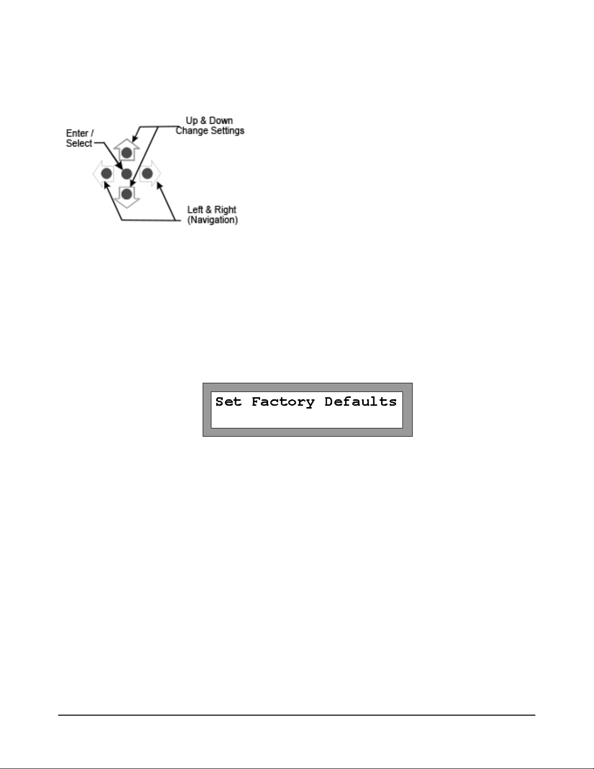
2.4 Close-Up of Controls & Display .................................................................................. 7
3 INSTALLATION ............................................................................................8
3.1 Receiving Instructions .................................................................................................. 8
3.2 Physical Location .......................................................................................................... 8
3.3 Electrical Connections .................................................................................................. 8
3.4 Signal Connections ....................................................................................................... 8
3.5 RS-232 Controller Requirements ................................................................................. 8
3.6 Ethernet ..........................................................................................................................9
4 FEATURES AND FUNCTIONS .................................................................10
4.1 Buttons ......................................................................................................................... 10
4.2 Reset ............................................................................................................................10
4.3 Test Points .................................................................................................................... 10
4.4 RF Inputs and Outputs ................................................................................................ 10
4.5 Power In .......................................................................................................................10
4.6 RS-232 Communication Ports .................................................................................... 11
4.7 Web Browser Interface ................................................................................................ 11
5 OPERATING MODES ................................................................................13
5.1 Initial Operation ...........................................................................................................13
5.2 Manual Mode ................................................................................................................13
5.3 Remote Mode ............................................................................................................... 14
Page 2 of 22 AT1700 series Manual D07-00-066P Rev. A00

6 CONFIGURATION MODE ..........................................................................15
6.1 UI Timeout Operation .................................................................................................. 17
6.2 Trigger Mode ................................................................................................................ 17
7 SERVICE AND SUPPORT .........................................................................19
7.1 Technical Support ........................................................................................................ 19
7.2 Warranty Information ................................................................................................... 19
8 PRODUCT SPECIFICATIONS ...................................................................20
8.1 GENERAL SPECIFICATIONS .................................................................................... 20
8.2 ELECTRICAL SPECIFICATIONS ............................................................................... 21
8.3 MECHANICAL & ENVIRONMENTAL SPECIFICATIONS .......................................... 22
Page 3 of 22 AT1700 series Manual D07-00-066P Rev. A00

1 GENERAL INFORMATION
1.1 Overview
The AT1700 series multiplexer switch offers a high performance, cost effective solution for broadband RF switch-
ing in headend environments. These switches are ideal for test measurement systems, such as the realWORX
monitoring system, where multiple CATV signals need to be tested through the same spectrum analyzer. The
1700 series is compatible with the AT2500HM series analyzers as well as with previous AT2000HM series spec-
trum analyzers.
Switch control is provided via serial port or manual control.
1.2 Disclaimer
Information in this document is subject to change without notice and does not represent a commitment on the
part of VeEX Inc. The software and/or hardware described in this document are furnished under a license agree-
ment or nondisclosure agreement. The software may be used or copied only in accordance with the terms of the
agreement. It is against the law to copy the software on any medium except as specically allowed in the license
or nondisclosure agreement. The purchaser may make one copy of the software for backup purposes. No part
of this manual and/or hardware and/or software may be reproduced or transmitted in any form or by any means,
electronic or mechanical, including photocopying, recording, or information storage and retrieval system, for any
purpose other than the purchaser’s personal use, without the express written permission of VeEX Inc. Through-
out this book, trademarked names are used in an editorial manner only and to the benet of the trademark owner,
with no intention of infringement of the trademark. Where such designations appear in this book, they have been
printed with initial capital letters.
VeEX and the VeEX logo, are registered trademarks of VeEX INC.
Copyright 2014 VeEX, Inc. All rights reserved.
Disclaimer: Contents subject to change without notice.
Page 4 of 22 AT1700 series Manual D07-00-066P Rev. A00

2 GETTING STARTED
2.1 Product Overview
The VeEX Inc. AT1700 Series comprises the AT1701 (16x1) and AT1702 (16x2) Multiplexers.
The AT1701 Multiplexer has 16 RF input ports and 1 output port. The output port can select any one of the inputs
or can be set to a NO SELECT (i.e. all-off) state.
The AT1702 Multiplexer has 16 RF input ports and 2 independently controlled output ports. Essentially it is two
16-to-1 multiplexers sharing the 16 inputs. Each of the output ports can select one of the inputs or can be set in
a NO SELECT (i.e. all-off) state.
All ports have a bandwidth of 1 GHz, a nominal 10 dB gain and >50 dB isolation.
Multiplexers can either be cascaded or outputs combined for exible selection of one signal source from a mul-
tiplicity of sources.
The AT1700 series is housed in a 1 RU, 12” deep chassis. Each unit has its own external power source.
The output ports can be controlled independently via the front panel buttons or remotely through an RS-232
connection. Communication IN and OUT connectors are provided for connecting to the controller and for “Daisy
Chaining” communications from one unit to the next.
The AT1700 switches may be used in combination with previous model AT1600 switches. Be sure that the com-
munications conguration matches both models.
Page 5 of 22 AT1700 series Manual D07-00-066P Rev. A00

1-8 RF In 8-16 RF In
A & B
RF Out
DC
Power
2.2 Front Panel
Status Indicator
An LED is located behind the VeEX Logo in the center of the AT1700 front panel and is powered on when the unit
is connected to the main power source.
2.3 Rear Panel
Page 6 of 22 AT1700 series Manual D07-00-066P Rev. A00

2.4 Close-Up of Controls & Display
Enter /
Select
Up & Down
Change Settings
Left & Right
(Navigation)
Left & Right Arrows are for navigation and sequence from screen to screen. Up and Down arrows increment or
decrement the current selected setting. The Center button selects the highlighted item and is used to terminate
changes (Enter).
Page 7 of 22 AT1700 series Manual D07-00-066P Rev. A00

3 INSTALLATION
3.1 Receiving Instructions
Inspect the shipping container and contents for damage. Notify VeEX Inc. immediately of any shipping damage.
Verify the contents of the package.
Each container should include the following:
AT1701 AT1702
AT1701 or AT1702 Multiplexer 1 1
Power Adapter 1 1
DB9F-to-DB9M cable 6’ 1 2
3.2 Physical Location
The AT1700 series is intended for rack-mount installation, and for indoor use only.
See Operating Specications for environmental requirements. As is general practice, the RF cables should be
kept to a minimum length to minimize their impact on measurement results.
3.3 Electrical Connections
The unit is powered from an external power supply whose input is connected to the AC mains and whose output
is connected to the unit. The power supply is auto-ranging from 100VAC to 240VAC, 47 to 63 Hz.
The AT1700 has no ON-OFF switch. It is powered on or off by connecting or disconnecting the power source,
either at the AC mains or at the DC power connection to the unit.
WARNING! Always use a three-pronged AC power cord (supplied with the product) and insert only into a proper-
ly grounded three-pronged receptacle. Failure to ensure proper grounding may expose users to a shock hazard
may damage the product and shall void the warranty.
Note: Any attached equipment (customer supplied) must be grounded to the same protective
ground as the Multiplexer.
3.4 Signal Connections
All signal connections made to both input and output ports (“F” connectors) must:
1. Maintain proper ground continuity.
2. Be stripped of any AC or DC component, common in “cable powering” techniques.
Note: At no time should “cable powering” (24 to 90 VAC or VDC) be applied to any of the sig-
nal ports. Doing so may cause irreparable damage to the unit and will void the warranty.
3.5 RS-232 Controller Requirements
There are no specic requirements of the controller other than it must be equipped with an RS-232 communica-
Page 8 of 22 AT1700 series Manual D07-00-066P Rev. A00

tions port and connected with appropriate cabling.
Controller requirements will be dictated by the software application used to control the multiplexer.
Note: Any controller equipment (customer supplied) shall be grounded to the same protective
ground as the Multiplexer.
3.6 Ethernet
Before the Ethernet can be used, the IP address needs to be setup for your network. The default IP address, as
shipped for the factory, is 192.168.1.1. The Ethernet port may be congured from the front panel.
Press the Left or Right arrow keys until the IP address screen is displayed.
Use the Up & Down arrow keys to select STATIC or DHCP.
When STATIC is selected use the Left or Right arrow key to select the 2ndline IP address and use the Up and
Down arrows to sequence each digit in the IP address until the desired IP is displayed.
Press ENTER.
In addition, the Subnet Mask and Gateway must be setup.
From the IP Address screen, press the Left or Right arrow key to display the Mask & Gateway setup screen.
Press Enter and then use the Left and Right arrow keys to navigate to the desired digit to edit and use the Up
and Down arrow keys to select the desired digit. Repeat this process for each digit until the desired Subnet Mask
is displayed.
Press ENTER and use the Left and Right arrow keys to select the Gateway IP address and edit it as needed.
If DHCP is selected, the AT1700 will obtain an IP address, Subnet Mask and Gateway from your DHCP server.
Note that setup may now be completed via a simple web browser connection. See the Web
Browser Interface section 4.7.
Page 9 of 22 AT1700 series Manual D07-00-066P Rev. A00

4 FEATURES AND FUNCTIONS
4.1 Buttons
The AT1700 has a group of ve buttons for manual control and to control the conguration of the AT1700 multi-
plexer.
Left & Right Arrows are for navigation and sequence from screen to screen. Up and Down arrows increment or
decrement the current selected setting. The Center button selects the highlighted item and is used to terminate
changes (Enter).
4.2 Reset
The AT1700 may be returned to the original factory default setting by using the Left or Right arrows to scroll the
display to the “Set Factory Defaults” screen and pressing the center Enter button. This resets all parameters to
the Factory Default setting. Complete conguration is required following this step.
4.3 Test Points
A -20 dB Test Point (female “F” connector) is provided for each Output Port and is located on the front panel for
easy access.
4.4 RF Inputs and Outputs
Sixteen 1 GHz bandwidth RF inputs are provided. The AT1702 has 2 RF outputs, one for each of the internal 16-
to-1 multiplexers. As a result each output can be independently connected to any one of the shared RF inputs,
passing that signal through to the output at unity gain.
Note: At no time should “cable powering” ( 24 to 90 VAC or VDC) be applied to any of the sig-
nal ports. Doing so may cause irreparable damage to the unit and will void the warranty.
4.5 Power In
Power In is provided for powering the unit from the AC adapter provided. No other power source should be uti-
lized unless it is provided by VeEX. An Optional 48 V DC power adapter is available.
Page 10 of 22 AT1700 series Manual D07-00-066P Rev. A00
Ce manuel convient aux modèles suivants
1
Table des matières
Autres manuels VeEX Changer


