
UTEK CRHE-V Guide de démarrage rapide

CRHE-V
indoor air quality and energy saving
MANUALE DI INSTALLAZIONE, USO E MANUTENZIONE
GUIDE FOR INSTALLATION, USE AND MAINTENANCE
UNITÀ DI VENTILAZIONE con RECUPERO DI CALORE per TERZIARIO E INDUSTRIA
HEAT RECOVERY VENTILATION UNITS for COMMERCIAL and INDUSTRIAL BUILDINGS

Gentile Cliente
Grazie per l’attenzione al prodotto UTEK, progettato
e realizzato per garantire all’Utilizzatore valori reali:
Qualità, Sicurezza e Risparmio sui consumi.
Dear Customer
Thanks for your attention to the product UTEK ,
designed and manufactured to ensure the real
values to the User : Quality, Safety and Savings on
working.
INDICE
NORME SICUREZZA E MARCHIATURA CE
RISCHI RESIDUI
RICEVIMENTO DELLA MERCE
MOVIMENTAZIONE
IMMAGAZZINAMENTO
CONDIZIONI DI INSTALLAZIONE
INSTALLAZIONE DELL’UNITÀ A SOFFITTO
INSTALLAZIONE DELL’UNITÀ A PAVIMENTO
NORME DI MANUTENZIONE
POSSIBILI CONFIGURAZIONI
MANUTENZIONE|PULIZIA FILTRI E SCAMBIATORE
CONFIGURAZIONE DELL’UNITÀ IN CANTIERE
INSTALLAZIONE IN CANTIERE DEL KIT ELETTRICO
INSTALLAZIONE IN CANTIERE DEL KIT BATTERIA
MONTAGGIO SCARICO CONDENSA
INSTALLAZIONE ACCESSORI
COLLEGAMENTI ELETTRICI
MESSA IN SERVIZIO DELL’UNITÀ
FERMO PROLUNGATO
ANOMALIE DI FUNZIONAMENTO
MONTAGGIO E SMONTAGGIO
SMALTIMENTO
INDEX
SAFETY RULES AND CE MARKING
RESIDUAL RISKS
RECEIPT OF GOODS
HANDLING
STORAGE
INSTALLATION CONDITIONS
INSTALLATION OF THE CEILING UNIT
INSTALLATION OF THE FLOOR UNIT
MAINTENANCE RULES
POSSIBLE CONFIGURATIONS
MAINTENANCE|CLEANING OF FILTERS AND EXCHANGER
CONFIGURATION OF THE UNIT ON SITE
INSTALLATION OF THE ELECTRIC KIT ON SITE
INSTALLATION OF THE BATTERY KIT ON SITE
CONDENSATE DISCHARGE ASSEMBLY
ACCESSORY INSTALLATION
ELECTRICAL CONNECTIONS
COMMISSIONING THE UNIT
PROLONGED STOP
OPERATING ANOMALIES
ASSEMBLY AND DISASSEMBLY
DISPOSAL
pag.3
pag.3
pag.3
pag.4
pag.4
pag.4
pag.5
pag.6
pag.7
pag.7
pag.8
pag.10
pag.12
pag.14
pag.15
pag.16
pag.17
pag.17
pag.17
pag.18
pag.20
pag.20
pag.3
pag.3
pag.3
pag.4
pag.4
pag.4
pag.5
pag.6
pag.7
pag.7
pag.8
pag.10
pag.12
pag.14
pag.15
pag.16
pag.17
pag.17
pag.17
pag.18
pag.20
pag.20
2

3
DIMESIONI BANCALE [mm]
PESO LORDO [Kg]Lunghezza Larghezza Altezza
UNITÀ
1800
2000
2300
2450
2650
2800
2930
860
1060
1070
1160
1560
1460
2010
900
1000
1210
1410
1410
1550
1550
120
162
251
298
386
455
728
CRHE-H 700
CRHE-H 1100
CRHE-H 1600
CRHE-H 2500
CRHE-H 3200
CRHE-H 4500
CRHE-H 5600
PALLET DIMENSIONS [cm]
UNIT
120
162
251
298
386
455
728
CRHE-H 700
CRHE-H 1100
CRHE-H 1600
CRHE-H 2500
CRHE-H 3200
CRHE-H 4500
CRHE-H 5600
GROSS WEIGHT [Kg]Length Width Height
1800
2000
2300
2450
2650
2800
2930
860
1060
1070
1160
1560
1460
2010
900
1000
1210
1410
1410
1550
1550
NORME DI SICUREZZA E MARCHIATURA “CE”
Il contrassegno CE e la relativa dichiarazione di conformità
attestano la conformità alle norme comunitarie applicabili. CLA
S.r.l. si esime da ogni responsabilità per eventuali danni causati a
persone e cose derivanti dalla mancata osservanza delle norme
di sicurezza, nonché dalle eventuali modifiche apportate al
prodotto.
RISCHI RESIDUI
L’unità, prima di essere accesa, deve essere canalizzata.
Leggere attentamente il seguente manuale prima di
effettuare qualsiasi azione sulla macchina
DPI
RICEVIMENTO DELLA MERCE
Ogni prodotto viene controllato accuratamente prima di essere
spedito. All’atto del ricevimento occorre controllare che il prodot-
to non abbia subito danni durante il trasporto; Le unità vengono
posizionate su pallet e fissate allo stesso tramite viti e reggie; un
film protettivo protegge l’intera superficie della macchina.
L’etichetta dell’unità è sempre visibile sull’imballo e contiene le
seguenti informazioni:
- Indirizzo del fabbricante e marchiatura CE
- codice, matricola e numero d’ordine della macchina
- descrittivo
- informazioni su ventilatori e portata
Sul bancale è, inoltre, sempre presente una busta trasparente
contenente manuale dell’unità, manuale del controllo e schema
elettrico dell’unità.
SAFETY STANDARDS AND “CE” MARKING
The CE marking and the relevant declaration of conformity prove
the conformity to the applicable community regulations. CLA s.r.l.
are exemp-ted from any responsibility attributable to damage
caused to persons and things resulting from the non-compliance
with the safety standards and any product modifications.
REMAINING RISKS
The unit, before being switched on, must be ducting.
DPI
GOODS RECEPTION
Each product is carefully checked before shipping. On goods
reception, it is necessary to make sure that products have not
suffered any damages during transport. The units are put on
pallets and fixed to the same by screws and straps; a protective
film protects the entire surface of the units.
The unit label is always visible on the packaging and contains the
following information:
- Manufacturer's address and CE marking
- unit code, serial number and order number
- descriptive
- information on fans and flow rate
Applied on the pallet there is always a transparent envelope
containing the unit manual, control manual and wiring diagram.
Obbligatorio indossare le calzature di sicurezza
Read the following manual carefully before carrying
out any action on the unit
Obbligatorio indossare i guanti protettivi
Obbligatorio indossare la protezione degli occhi
It is mandatory to wear safety shoes
It is mandatory to wear protective gloves
It is mandatory to wear eye protection

IMMAGAZZINAMENTO
Conservare l’unità in un luogo riparato, senza eccessiva umidità e
non soggetto a forti sbalzi termici al fine di evitare la formazione di
condensa all’interno dell’unità.
CONDIZIONI DI INSTALLAZIONE
Installazione all’interno o all'esterno di edifici con temperatura
ambiente compresa tra -15° e +50°C. Da evitare:
- aree in prossimità di fonti di calore, vapore, gas o liquidi infiam-
mabili e/o esplosivi, aree particolarmente polverose, vicinanza di
sorgenti d’acqua come vasche, docce o piscine.
- non toccare l’apparecchio con mani o piedi bagnati o umidi.
Da fare:
- utilizzare l’apparecchio solo per l’uso per il quale è stato espres-
samente costruito. Il costruttore non può essere considerato
responsabile per eventuali danni derivanti da usi impropri o errati.
- considerare un’area dove la mandata d’aria ed il rumore
dell’unità non rechino disturbo ai vicini;
- considerare una posizione che rispetti gli spazi minimi (come
indicato nel presente manuale);
- considerare una posizione che non ostruisca passaggi o ingressi;
- Il grado di protezione dell’unità è IP20.
In caso di installazione all’esterno:
- collocare l’unità in luogo riparato da agenti atmosferici oppure
utilizzare l'apposito tettuccio parapioggia (se necessario congiun-
tamente alle apposite cuffie di prot zione con rete). In questo
caso il grado di protezione diventa IP22.
- Verificare che l’unità sia a livello
STORAGE
Store the unit in a sheltered place, without excessive moisture and
not subject to sudden changes of temperature in order to prevent
condensation inside the unit.
INSTALLATION CONDITIONS
Installation allowed inside the buildings or outdoor, with tempera-
ture between -15° to +50° C To avoid:
- areas near sources of heat source, steam or liquid flammable
and/or explosives gases, dusty areas, proximity to water sources
such as baths, showers or swimming pools
- Do not touch the device with wet or damp hands or feet.
To consider:
- use the device only for the use for which it was built. The manu-
facturer can not be held responsible for any damage caused by
improper or incorrect use.
- consider an area where the air flow and noise of the unit don’t
disturb the neighbors;
- minimum space required for the maintenance (as defined below);
- a position that does not block passageways or entrances;
- The protection degree is IP20.
In case of outdoor installation:
- place the unit in a place sheltered from the weather otherwise,
use the weather protective roof (if required, use the weather
protection cowl too). The protection degree changes in IP22
- Check that the unit is level
4
RUMORE DALLA CASSA (dB) RUMORE NEL CANALE (dB)
UNITÀ
52,2
51,4
58,6
59,8
63,2
68,4
73,3
55,9
56,2
64,7
64,8
68,4
73,4
77,9
CRHE-H 700
CRHE-H 1100
CRHE-H 1600
CRHE-H 2500
CRHE-H 3200
CRHE-H 4500
CRHE-H 5600
POTENZA (W)
UNITÀ
MOVIMENTAZIONE
Prima di spostare il prodotto, accertarsi che il mezzo utilizzato sia di
portata adeguata (vedi tabella pesi lordi nel capitolo “RICEVI-
MENTO DELLA MERCE”). Per il sollevamento servirsi di sollevatore a
forche, sollevando il pallet. Il sollevamento a mano massimo è
specificato nella norma 89/391/CEE e successive. Il pallet è
inforcabile sul lato lungo
HANDLING
Goods must be displaced by the correct equipment witha
suitable carrying capacity (see gross weight table in the chapter
"RECEIPT OF GOODS"). For pallet lifting use forklifts. According to
the standard 89/391/CEE and following standards. The pallet is
centrally forkable on all 4 sides;
A
UNITÀ|UNIT Dimensioni|Dimensions [mm]
B
C
ØØ
CRHE-V 700
/ENT
1475 760 660 200
CRHE-V 1100
/ENT
CRHE-V 1600
/ENT
1645 960 760 250
104
140
Peso|Weight[kg]
C
A
Ø
1
/
2
"
g
a
s
Ø
B
100
160
160
CRHE-V 2500
/ENT
2150 1060 1180 355
CRHE-V 3200
/ENT
2305 1460 1180 450
268
352
CRHE-V 4500
/ENT
2465 1360 1320 500
CRHE-V 5600
/ENT
2545 1910 1320 560
406
674
2000 970 980 355 222
2 x 145
2 x 170
2 x 448
2 x 448
2 x 715
2 x 1270
2 x 1400
CRHE-H 700
CRHE-H 1100
CRHE-H 1600
CRHE-H 2500
CRHE-H 3200
CRHE-H 4500
CRHE-H 5600
NOISE FROM THE CASE (dB) NOISE IN TO THE DUCT (dB)
UNIT
52,2
51,4
58,6
59,8
63,2
68,4
73,3
55,9
56,2
64,7
64,8
68,4
73,4
77,9
CRHE-H 700
CRHE-H 1100
CRHE-H 1600
CRHE-H 2500
CRHE-H 3200
CRHE-H 4500
CRHE-H 5600
POWER (W)
UNIT
2 x 145
2 x 170
2 x 448
2 x 448
2 x 715
2 x 1270
2 x 1400
CRHE-H 700
CRHE-H 1100
CRHE-H 1600
CRHE-H 2500
CRHE-H 3200
CRHE-H 4500
CRHE-H 5600
spazio forche muletto
forklift space

5
manutenzione straordinaria e sostituzione
di batteria ad acqua o di riscaldatore elettrico
UNITÀ|UNIT A
[mm]
B
[mm]
D
[mm]
E
[mm]
CRHE-V 700
760 985 420 240
CRHE-V 1100
860 1125 470 270
CRHE-V 1600
1080 1320 600 400
CRHE-V 2500
1280 1550 680 350
CRHE-V 3200
1280 1625 680 430
CRHE-V 4500
1420 1785 750 430
CRHE-V 5600
1420 1865 750 430
C
[mm]
E
[mm]
CRHE-V 700
800
CRHE-V 1100
850
CRHE-V 2500
950
CRHE-V 3200
1320
CRHE-V 4500
1320
CRHE-V 5600
1830
F
[mm]
460
510
720
720
790
790
E
B
A
D
350
min.
350
min.
280
800
280
F
C
E
240
270
CRHE-V 1600
1000 630
430
350
430
430
430
INSTALLAZIONE DELL’UNITA’
INSTALLATION OF THE UNIT
INSTALLAZIONE ORIZZONTALE A PAVIMENTO
L'unità CRHE-V è dotata di apposito basamento. Collocata
l'unità nella giusta posizione, effettuare il collegamento con la
canalizzazione, l'allacciamento alla rete elettrica tramite
quadro elettrico e il fissaggio del tubo scarico condensa sul lato
d'espulsione aria. (In caso di unità con batteria ad acqua,
anche sul lato di mandata aria)
HORIZONTAL FLOOR INSTALLATION
The heat recovery unit CRHE-V is equipped with special suppor-
ting basament. Put the unit in the right position, carry out the
connection to the ducting, the connection to the supply mains
through the electrical panel and the condensate discharge
pipe fastening on the air exhaust side. (In case of unit with water
coil, also on the supply air side)
INSTALLAZIONE A PAVIMENTO | FLOOR INSTALLATION
Spazi minimi necessari per le operazioni di manutenzione (mm)
Minimum space required for the maintenance (mm)
UNITÀ|UNIT
Installare l’unità attraverso mezzi appropriati (peso da 104 Kg fino a 674 Kg) al fine di evitare rischi durante la procedure di movimentazione
del carico.
Install the unit with appropriate means (weight from 104 Kg until 674 Kg). in order to avoid risks during the load handling procedures
DPI: dispositivi di protezione individuale
PPE: Personal Protective Equipment
Questa operazione deve essere svolta SOLO DA PERSONALE QUALIFICATO
This operation must be performed ONLY BY QUALIFIED STAFF

CRHE-H vista laterale| CRHE-H side view
CRHE-H specchiato vista laterale |CRHE-H mirrored side view
6
POSSIBILITÀ DI CONFIGURAZIONE / CONFIGURATION POSSIBILITY
Gli schemi elettrici sono disponibili sul sito www.utek-air.it
Electrical diagrams are available on the website www.utek-air.it
Questa operazione deve essere svolta SOLO DA PERSONALE QUALIFICATO
This operation must be performed ONLY BY QUALIFIED STAFF
DPI: dispositivi di protezione individuale
PPE: Personal Protective Equipment
ATTENZIONE: prima di effettuare una qualsiasi procedura sull’unità assicurarsi che non vi sia tensione
CAUTION: Before performing any procedure on the unit make sure that there is no voltage
immissione
supply air
estrazione
exhaust air
immissione
supply air
estrazione
exhaust air
espulsione
expulsion
rinnovo
fresh air
espulsione
expulsion
rinnovo
fresh air
NORME DI MANUTENZIONE
Le protezioni di sicurezza non devono essere rimosse se non
per assoluta necessità di lavoro; nel qual caso dovranno
essere immediatamente adottate idonee misure atte a
mettere in evidenza il possibile pericolo. Il ripristino sul prodot-
to di dette protezioni deve avvenire non appena vengono a
cessare le ragioni della temporanea rimozione. Tutti gli
interventi di manutenzione (ordinaria e straordinaria) devono
essere effettuati a macchina ferma ed alimentazione elettri-
ca ecc. disinserite. Per scongiurare il pericolo di possibili
inserimenti accidentali, apporre sui quadri elettrici, sulle
centrali e sui pulpiti di comando cartelli di avvertimento con
la dicitura “Attenzione: comando escluso per manutenzione
in corso”. Prima di collegare il cavo di alimentazione elettrica
alla morsettiera verificare che la tensione di linea sia idonea
a quella riportata sulla targhetta posta sulla macchina.
L’apparecchio deve essere utilizzato solo da personale
autorizzato. Il suddetto personale, oltre a dover osservare le
vigenti disposizioni di legge in materia di prevenzione dagli
infortuni, deve rispettare le istruzioni qui di seguito riportate:
- Deve indossare adeguato abbigliamento antinfortunistico;
- E’ obbligatorio l’uso di cuffie afoniche quando il rumore
supera il limite ammissibili;
- Deve verificare l’esistenza di un interblocco che impedisca
l’avviamento della macchina da parte di altre persone.
MAINTENANCE REGULATIONS
The safety protections must not be removed except for
absolute necessity of work; in which case suitable measures
must be taken immediately to highlight the possible
danger.The restoration of these protections on the product
must take place as soon as the reasons for the temporary
removal cease. All maintenance interventions (ordinary and
extraordinary) must be carried out with the machine stopped
and the power supply, etc. disconnected. To avoid the
danger of possible accidental insertions, put warning signs on
the electrical panels, on the control units and on the pulpits
with the words "Warning: command excluded for maintenan-
ce in progress". Before connecting the power supply cable to
the terminal block, check that the line voltage is suitable for
that indicated on the plate located on the unit. The applian-
ce must only be used by authorized personnel. The mainte-
nance personnel, besides having to comply with current
legislation regarding accident prevention must observe the
following instructions :
- wear suitable accident prevention clothes
- when the noise exceeds the admissible levels, use protection
headsets
- machine must be provided with an interlock which prevents
of the machine by non-authorized persons

MANUTENZIONE E PULIZIA FILTRI E SCAMBIATORE
MAINTENANCE AND CLEANING OF FILTERS AND HEAT EXCHANGER
7
1 2
34
56
La pulizia di Filtri e Scambiatore è consigliata almeno una volta all’anno; Seguire le indicazioni che vengono visualizzate
sul pannellino di controllo.|Cleaning of Filters and Exchanger is recommended at least once a year; Follow the indications
that appear on the control panel

8
7
9
8
Questa operazione deve essere svolta SOLO DA PERSONALE QUALIFICATO
This operation must be performed ONLY BY QUALIFIED STAFF
PRESTARE ATTENZIONE DURANTE L’ESTRAZIONE
E LA MOVIMENTAZIONE DELLO SCAMBIATORE.
PAY ATTENTION DURING THE EXTRACTION
AND HANDLING OF THE EXCHANGER.
DPI: dispositivi di protezione individuale
PPE: Personal Protective Equipment
ATTENZIONE: prima di effettuare una qualsiasi procedura sull’unità assicurarsi che non vi sia tensione
CAUTION: Before performing any procedure on the unit make sure that there is no voltage
9
1 2
34
56
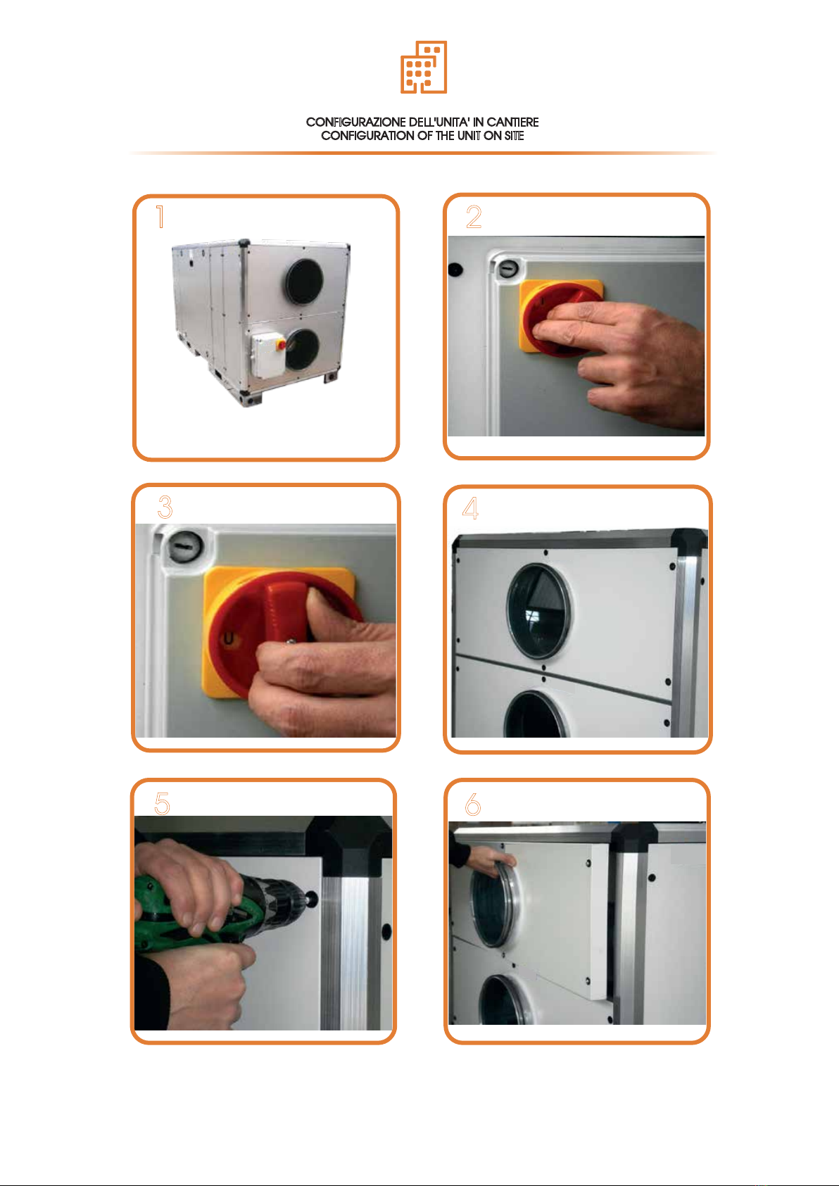
CONFIGURAZIONE DELL'UNITA' IN CANTIERE
CONFIGURATION OF THE UNIT ON SITE

10
7 8
910
11 12
Table des matières
Autres manuels UTEK Système de chauffage


