• Please do not exceed the maximum discharge current listed in the table under the "Specications"
section. Do not discharge the battery with Max Discharge Current several times in succession.
The battery can be discharged up to 150A @ 30 mins in emergency situations only. Repetitive
discharging at this rate can lead to battery damage and may void product warranty.
• The maximum continuous power should not exceed 1280W (i.e. battery can support 1000W
inverter) and the maximum continuous load should not exceed 1100W.
• Do not mix a new battery with a used battery in the same conguration.
Discharging Instructions
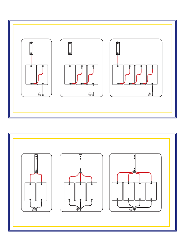
Series and Parallel Connection Instructions
• Please ensure battery is fully charged before connecting in series or parallel.
• If the battery top cover has a label showing number 1-# (i.e. 1-1, 1-2, 1-3 etc.) this means
that the batteries are grouped in manufacturing factory to ensure consistency in case
batteries are connected in series or parallel. The rst number is the group number. The
second number is the sequence within the group. Please do not mix dierent groups of
batteries.
• The battery can be connected in both series and parallel up to 4 batteries. For example, (4)
12V100Ah batteries connected in parallel can create a 12V400Ah battery bank. The parallel
wiring for the positive and negative post must be the same gauge and length (4 AWG - 16 inches.)
If you want to use them in series and in parallel concurrently, please contact Ultimate Power (UP.)
If not wired as per guidance from UP, then UP reserves the right to nullify and void product
warranty. Please contact UP for a solution.
–4–
• Do not leave battery charger connected to maintain or store the battery unless specically
programmed for 3-stage LiFePO4 battery charger. Leave charger unattended at your own risk.
• To charge a battery with a lead-acid charging system, make sure the charging voltage is <14.6V (+/-
.2V). If charging in a series, please ensure the charging voltage is <14.6V times the series number
(e.g. the charging voltage for a 4 Series Battery Charge should be <58.4V, and the charging
current must follow the instruction outlined in "Charging Instructions.")