Tunstall Lifeline Digital Manuel utilisateur
English Doc 346 80 21-69. Version 2 Revision 01.2023 - SW
Lifeline Digital
Art. 022-25-9xx
Quickstart guide
DMP

Please Note:
This an international guide and may contain features and functions not
currently available in your region.
Please contact your Tunstall Healthcare representative for more information.

Table of Contents
1. Overview ..................................................................................................................................................... 4
1.1. Version ................................................................................................................................................. 4
2. Install Lifeline Digital .................................................................................................................................... 5
3. Connect a peripheral ................................................................................................................................... 7
4. Device Management Platform (DMP) ............................................................................................................ 8
4.1. Log in to DMP and access device settings .............................................................................................. 8
4.2. Common settings .................................................................................................................................. 9
4.3. Configure cellular network settings and Access Point Name (APN) ........................................................... 9
4.4. Configure device connectivity methods ................................................................................................ 10
4.5. Configure IP alarms ............................................................................................................................. 10
4.6. Configure SIP accounts ........................................................................................................................ 11
4.7. Save settings ...................................................................................................................................... 12
4.8. Logout ............................................................................................................................................... 12
A. Contact details .......................................................................................................................................... 13

1. Overview
1
11
7
6
54
2
3
8
9
10
12 13 14
15 16 17 19 2018
1. Red Alarm button
2. Green Cancel button
3. Yellow Extra button
4. Green LED indicator
5. Yellow LED indicator
6. Red LED indicator
7. NFC
8. Microphone
9. IR receiver
10. Speaker
11. Back cover
12. On/Off (I/0) switch
13. Antenna connector
14. 2x USB 2.0 ports
15. Ethernet/network con-
nector (RJ45 port)
16. 4. Power connector 12V
(RJ11 port)
17. Cable slot
18. Security screw (T10) for
battery slot
19. Battery slot
20. SIM card holder inside
battery slot
1.1. Version
This document reflects DMP version 4.3.
4

2. Install Lifeline Digital
a) Remove the back cover (1).
1
b) For Ethernet/wired IP connectivity, connect Lifeline
Digital to a local router or Ethernet socket:
i. Insert an Ethernet cable into the Ethernet/Net-
work (RJ45) connector on the device (2).
ii. Connect the other end of the Ethernet cable to a
local router or Ethernet socket.
2
c) For cellular connectivity, insert the SIM card provided
by your supplier or Tunstall.
If the device is delivered with a pre-installed SIM
card, skip this step.
i. Unscrew the security screw using a T10 torx
screwdriver (3).
ii. Pull out the battery holder from the battery slot
(4).
3
4
iii. Insert the SIM card (standard/mini-SIM size) in
the SIM card slot (5). Make sure that the metallic
chip is facing down and that the SIM card notch
is aligned as shown in the illustration.
iv. Insert the battery holder into the battery slot (6).
If it is a tight fit, carefully press down on the SIM
card with your finger.
5
6
v. Screw the security screw back in place using the
T10 torx screwdriver.
d) Connect Lifeline Digital to mains power:
CAUTION
Only use a power adapter that is in-
tended for use with this product and
that has been supplied by . Make
sure that the power adapter has the
following output specification:
• +12.0V 1.0A, (12.0W)
•
PIN 2“+”
PIN 3“-”
i. Insert the mains power adapter cable into the
12V socket (7).
ii. Connect the mains power adaptor to a wall sock-
et (8).
7
8
e) Set the ON/OFF switch to 1 (ON) to power up the
device (9).
The green and yellow LED indicators starts to flash
rapidly to indicate start-up progress.
The device is ready when the LED indicators stop
flashing.
9
f) For devices with cellular connectivity, check to ensure
that cellular signal strength is sufficient:
5

i. Press and hold the green Cancel button (10),
then press and hold the red Alarm button (11)
and the yellow Extra button (12).
1012 11
ii. Release all buttons when the device emits a ris-
ing sound signal and announces "Programming
mode".
The LED indicators start chaser sequence and
the button LEDs flash in unison to indicate that
the programming mode is enabled.
iii. Press and hold the yellow Extra button (13).
13
iv. When the device announces "Four", release the
button.
The device announces the current signal
strength:
• “Cellular signal strength is One" for poor cel-
lular signal strength.
• "Cellular signal strength is Two"
• "Cellular signal strength is Three"
• "Cellular signal strength is Four"
• “Cellular signal strength is Five” for excellent
cellular signal strength.
v. If necessary, adjust position of the device to im-
prove cellular signal strength.
vi. Press the green Cancel button (14) to exit cellu-
lar signal test.
vii. Press the green Cancel button (14) again to exit
programming mode.
14
g) If the device is registered to Tunstall's Device Man-
agement Platform (DMP), you can manually connect
to DMP to download configuration and firmware up-
dates:
i. Press and hold the yellow Extra button (15) for
approximately 3 seconds.
15
ii. When the device emits a rising sound signal and
the yellow LED indicator starts to flash, release
the button.
The device attempts to connect to DMP and an-
nounces either:
• "Connected to DMP" when a connection is
established.
• "Connection attempt to DMP failed" if all con-
nection attempts fail.
When Lifeline Digital is ready it announces "Commu-
nication with DMP completed". This may take several
minutes depending on the network connection.
h) Replace the back cover.
6

3. Connect a peripheral
a) Press and hold the green Cancel button (1) then
press and hold the red Alarm button (2) and the
yellow Extra button (3).
13 2
b) When the device emits a rising sound signal and an-
nounces "Programming mode", release all buttons.
The LED indicators start chaser sequence and the
button LEDs flash in unison.
c) Press and hold the red Alarm button (4).
4
d) When the device announces “Auto pairing mode”,
you can either:
• Release the button to enable auto paring mode.
In auto paring mode the peripheral is stored in the
first available radio sensor position.
• Continue to hold the button until the device an-
nounces the number of the radio sensor position
you want to select, then release the button.
In manual pairing mode the peripheral is stored at
the selected radio sensor position.
e) When the device announces "Activate transmitter
now, activate/trigger the peripheral (5).
The device announces:
• “Operation succeeded” if the peripheral was suc-
cessfully connected.
• “Battery low” if the battery of the peripheral is low.
• “Operation failed” followed by an error code if the
connection failed.
• “Error code One” if the device memory is full.
• “Error code Two” if the peripheral is already con-
nected to the device.
5
f) Press the green Cancel button (6) to save current
settings and exit.
6
7
4. Device Management Platform (DMP)
Tunstall’s Device Management Platform (DMP) is a cloud-based system that provides remote management, config-
uration and monitoring of connected devices. From DMP it is possible to manually configure settings or apply
preconfigured templates to one or several devices. DMP can also distribute configuration and firmware updates.
To configure Lifeline Digital using DMP you require:
• A username and password
• If your organization enforce two-step verification, you must set up Google Authenticator, for more information refer
to DMP User manual.
• A list of all values and parameter settings to be configured. Do not change any settings or values unless advised by
your supplier or Tunstall
4.1. Log in to DMP and access device settings
To log in to DMP and access device settings:
a) Go to the DMP login page.
The web address (URL) is provided by your organisa-
tion, supplier or Tunstall.
NOTE
Bookmark the web address (URL) for
faster access in the future.
b) Enter your username and password then click LOGIN
DMP opens the Start page.
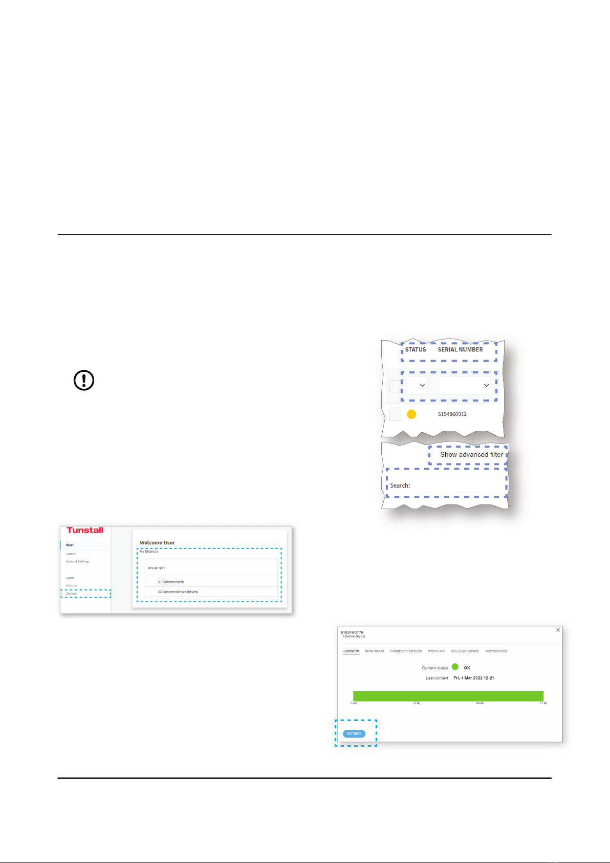
c) Under My Districts, click on the district that you want
to view, or click Devices in the sidebar menu.
DMP opens the Devices page and displays a list of
devices.
d) You can search, sort and lter the list:
•Search the list by entering a text in the search field
•Sort the list by clicking a column header. Click
again to toggle between ascending and descend-
ing order
•Filter the list by selecting an option in the drop-
down list below a column heading
• Click Show advanced lter to enable additional
search and filter features
• If you have access to multiple districts and custom-
ers, click the District and Customer drop-down lists
to select the appropriate customer and district
e) Click on the device that you want to view or edit.
DMP opens the Device information window.
f) Click Settings to open the Device settings window.
The Common settings tab is the default view.
8
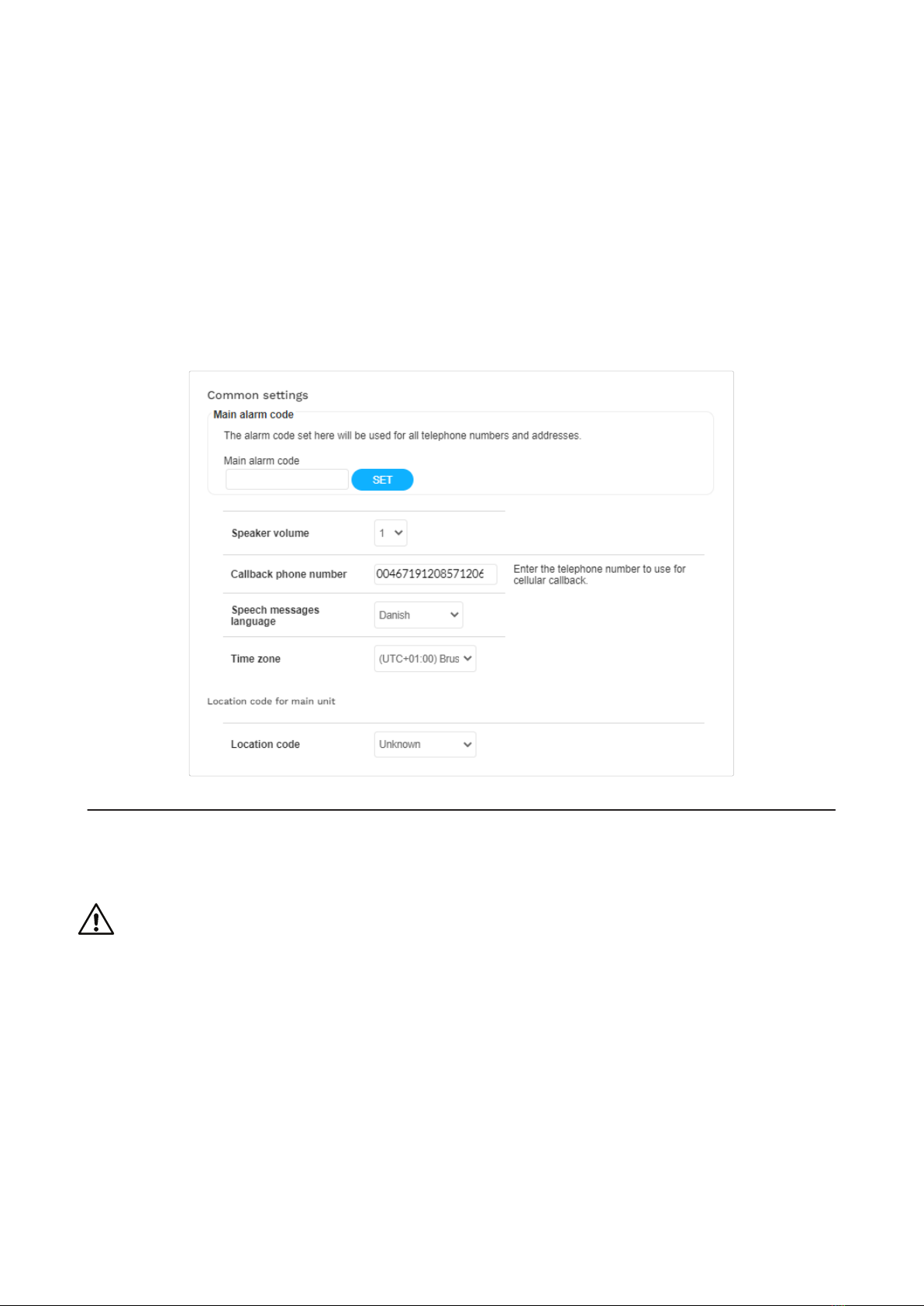
4.2. Common settings
To configure common settings:
a) Common settings is selected by default when you
click Settings in the Device information window, oth-
erwise go to Common settings.
b) If the same alarm code is to be used for all alarm
receivers or Alarm Receiving Centres (ARCs):
i. Enter the alarm code in the Main alarm code
field. The alarm code is used to identify the de-
vice at the Alarm Receiving Centre (ARC).
ii. Click Set.
The alarm code appears in all Alarm code fields.
c) Set the speaker volume in the Speaker volume drop-
down list.
d) For cellular callback, enter the telephone number
to use in the Callback phone number field. Use in-
ternational telephone number format, for example:
"+46[...]" or "0046[...]".
e) Select the correct time zone in the Time zone drop-
down list.
f) Select a location code in the Location code drop-
down list. The location code notifies the alarm receiv-
er or ARC where the device is located.
4.3. Congure cellular network settings and Access Point Name (APN)
CAUTION
Do not change settings or values unless advised by your supplier or Tunstall. Unauthorized changes
may disrupt communication and cause connectivity failure.
To configure cellular network settings:
a) Go to IP Alarms > GSM APN.
b) Under GSM, enter the APN of your network provider
in the APN field.
c) If required, configure PIN code:
i. Enter PIN code for the SIM card in the PIN code
field.
ii. Activate PIN code in the PIN mode drop-down
list.
d) If required, configure Internet settings:
i. Select authentication protocol in the Authentica-
tion mode drop-down list.
ii. Enter username in the Internet user field.
iii. Enter password in the Internet password field.
9

4.4. Congure device connectivity methods
To select device connectivity methods:
a) Go to IP alarms > Device Connectivity Methods.
b) Under Device connectivity methods, select the ap-
propriate connectivity methods:
•Ethernet
•Cellular
•WiFi
4.5. Congure IP alarms
To configure connection details for IP Alarms:
a) Go to IP Alarms > Connections and select an appro-
priate Address. Address n is typically reserved for
night redirection.
b) Enter the IP address or FQDN of the receiver in the
Address field.
c) Select a communication protocol in the Protocol
drop-down list:
•Tunstall IPACS
•SCAIP
•Homephone-SIP
•EN50134-9
NOTE
If the selected protocol does not
support an alarm or event type,
the alarm distribution moves on to
the next step in the distribution se-
quence.
d) Set the number of connection attempts to be made
for this address in the No. of attempts field.
10
Autres manuels pour Lifeline Digital
4
Table des matières
Autres manuels Tunstall Changer


