
Tufner T903 Manuel utilisateur

T903
Portable Static Weighing Indicator
User’s Manual
(4 Channels)
(6 Channels)
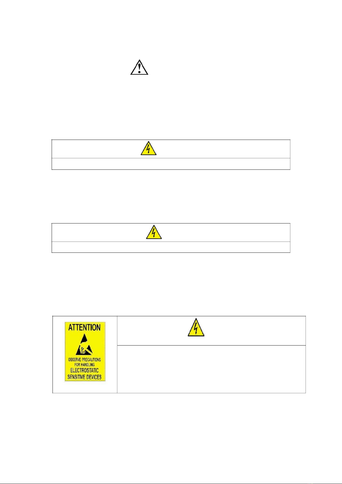
WARNING
Setting. Calibration Inspection and Maintain of the indicator is prohibited by Non-professional staff.
WARNING
Pls. make sure the weighing display have good ground in using.
Safety Instruction
For safety operation pls. follow the safety instruction.
WARNING
The indicator is the static and sensitive
equipment,cut off the power during electrical
connections, internal components touched by hand
is prohibited, and please take the measure of anti-
static.

LIST
LIST.......................................................................................................................................................... 1
1. PRODUCT INTRODUCTION...........................................................................................................1
1.1 MAIN FUNCTION............................................................................................................................................................ 1
1.2 TECHNICAL PARAMETER............................................................................................................................................ 1
1.3 DRAWING.......................................................................................................................................................................... 2
1.4 BATTERY INSTRUCTION.............................................................................................................................................. 2
2. INSTALLATION AND CALIBRATION...........................................................................................2
2.1 CHECK............................................................................................................................................................................... 2
2.2POWER SUPPLY CONNECTION...................................................................................................................................2
2.3 CONNECTION OF LOAD CELL AND INDICATOR....................................................................................................3
2.4 COMMUNICATION INTERFACE...................................................................................................................................4
3. BASIC OPERATION......................................................................................................................... 5
3.1 KEYPAD............................................................................................................................................................................. 5
3.2 POWER ON &OFF.........................................................................................................................................................6
3.3 ZERO OPERATION......................................................................................................................................................... 6
3.4 TARE OPERATION..........................................................................................................................................................6
3.5 UNIT SWITCH..................................................................................................................................................................7
3.6 CHECKING........................................................................................................................................................................7
3.7 SWITCHING...................................................................................................................................................................... 7
3.8 PRINTING..........................................................................................................................................................................7
4. CALIBRATION AND PARAMETER SETTING............................................................................ 7
4.1 ENTER SETTING............................................................................................................................................................. 7
4.2 STEP OF CALIBRATION OPERATION........................................................................................................................8
4.3 APPLICATION FUNCTION PARAMETERS SETTING CHART.................................................................. 9
5.SERIAL INTERFACE RECEPTION COMMAND........................................................................11
5.1 COMMAND 1................................................................................................................................. 11
5.2 COMMAND 2.................................................................................................................................12
6.PRINT FORMAT............................................................................................................................... 12
6.1 NORMAL PRINTING FORMAT.................................................................................................................................. 12
6.2 ACCUMULATIVE PRINTING FORMAT..................................................................................................................... 12
7.MAINTENANCE................................................................................................................................13
7.1 REGULAR ERROR AND SOLUTION.........................................................................................................................13
7.2 DAILY MAINTAIN...........................................................................................................................................................14
7.3PACKING LIST................................................................................................................................................................ 15

1
1. Product Introduction
1.1 Main Function
Portable Static Weighing Indicator MWI01 is designed for static axle scale. It can
connect with 1,2,3,4,5,6 weighing pads to weigh the truck. It owns manual weighing mode
and automatic weighing mode. It can be normal weighing or accumulative weighing.
Varied weighing ways to meet different requirements.
LCD display (size: 136mm x 36.5mm) show the real weight date on the weighing pad.
The unit KG/LB display can be adjusted by the key on the instrument. At same time, the
percentage of each pad on the total weighing is displayed too. Other function includes
tare, zero, print, save, check, delete.
The power supply by 7.4v/4400mAh battery and it can be recharged by 8.4v/1A
adapter. Built-in thermal printer, several printing formats; with RS232 interface for
computer; The calendar is in the software. Date and time can be checked easily. Easy
operation, high precision, good application.
1.2 Technical parameter
>> Sensitivity 0.5u
v/d
>> Input voltage -30~
30mV
>> Accuracy class III
>> Initial zero range ±10
%Max
>> Manually zero range ±2
% Max
>> Zero Range 100
% Max
>> Zero Tracking 0.5
d/s
>> Excitation circuit VDC
,6 wire connection,Maximum connect 24 load cell of 350Ω
>> AC power 100
~240VAC,50/60HZ
>> Operation temperature hum
idity -10℃~+40℃,≤90%RH
>> Storage temperature
-10℃~+40℃
2
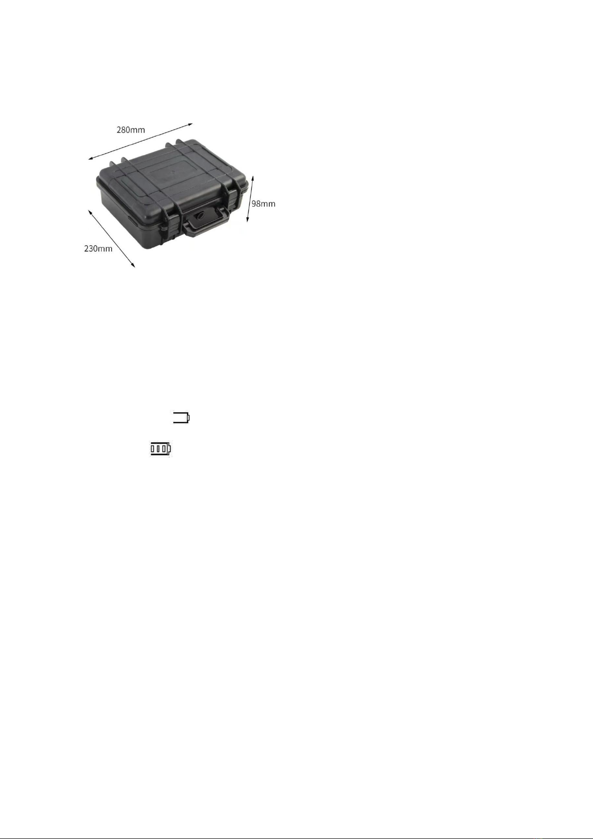
1.3 drawing
1.4 Battery instruction
1. when you use the internal battery first time,you should charge the battery fully,
to prevent low voltage resulted from self leakage of battery.
2. when the “ ” is flashing, it means low battery, pls. charge it in time.
3. when and no flashing, it means fully charged
4. if battery is not used for long time, take it out to avoid the leakage.
5. In order to keep the battery in best using condition, it is suggest that you fully
discharge the battery every month, the method is that using the indicator till it is
automatically power off.
2. Installation and calibration
2.1 Check
Open the box and check all items according to the packing list. If som missed or
broken, please contact with our company immediately.
2.2Power supply connection
The indicator is powered by adapter, you plug the adapter directly into the “DC” pin
at the back cover the indicator is ok.

3
2.3 Connection of load cell and indicator
The indicator can connect with 4 weighing pads or 24 pcs of load cells 350Ω at most.
Quick disconnect of load cell as below.
The number of weighing pads and load cells correspond to the weighing modes. If
the pads or load cells are connected at the right way, the indicator can’t work. Please pay
attention to the below.
Number of
Load cell connection
Weighing mode
weighing pad
1
LFW
[ModE 1]Setting “1”
2
LFW,RFW
[ModE 2]Setting “2”
3
LFW,LRW,RRW
[ModE 3]Setting “3”
4
LFW,RFW,LRW,RRW
[ModE 4]Setting “4”
5
LFW,RFW,LRW,RRW,
LFW/RFW
[ModE 5]Setting “5”
6
LFW,RFW,LRW,
RRW,LFW/RFW,RFW/LRW
[ModE 6]Setting “6”
Normal weighing mode and accumulative weighing mode can work with the printer
to print the weighing data.
Normal Weighing mode:
To set the printing format “1”, the indicator is in normal weighing mode. It can
connect 1/2/3/4/ pads to weigh and “Print” the weighing data and save.
Example:3 weighing pads connect with indicator to weigh the airplane.
a.
The pads should connect with LFW,LRW,RRW interfaces;
b.
parameter setting:working mode[ModE 3]setting “3”;printing format[PF - 1]setting
“1”;
c.
Drive the plane on the pads. Press “switch” button, indicator can display the total
weight and the weight of each pad and the percentage of each pad weight from the
total weight.If printing format setting”1”, the weighing data can print automatically
and save after stable.If printing format setting”0”, the weighing data will print and
save manually.
Accumulative weighing mode:
To set printing format ”2”, the indicator is in accumulative weighing mode. Now 2/4

4
pads should be connected with the indicator. And press ”store” button to accumulate
the axle weigh and print. Then press “printing” to print the final accumulative weight and

5
save.
Example:Two pads work with the indicator to weigh a truck with three axles.
a.
The pads should connect with LFW,RFW interfaces;
b.
Parameter setting:working mode[ModE 2] setting“2”;printing format[PF -
2]setting“2”;Axles [ALE - 3]setting“3”.
c.
Drive the first axle of the truck on the weighing pads. Press ”Switch” button,
indicator can display the axle weight and the each weight of the wheels and the
percentage of each wheel weight from the axle weight. If printing format setting “1”, the
weighing data can print and save automatically after weighing stable;If printing format
setting”0”, the weighing data will print and save manually by press “ store” button.
d.
Drive the second axle of the truck on the weighing pads and repeat the
operation same as step C, accumulate and print the second axle weight.
e.
Drive the second axle of the truck on the weighing pads and repeat the operation
same as step C, accumulate and print the third axle weight.
f.
After finishing the weight for three axles, if printing format setting”1”, the total
weight will print and save automatically; If printing format”0”, it will print manually by
press ”print” button.
2.4 Communication interface
RS232 :DB9 Pin definition as below.
Pin function and definition as bellows:
DB9 joint
Definition
Function
2
TXD
Sending data
3
RXD
Receiving data
5
GND
Ground interface

5
3. Basic operation
3.1 Keypad
LCD
Instruction
Weighing data
Kg/lb
Weighing unit: kg/lb
Percentage,show how many percentage the pad weight take on
the whole weight
Tare
Tare
Gross
Gross weight
Net
Net weight
The weighing data is stable
Weight is zero
LFW
The weight of the left front wheel
RFW
The weight of the right front wheel
LRW
The weight of the left back wheel
RRW
The weight of the right back wheel
Total
Go to accumulation mode
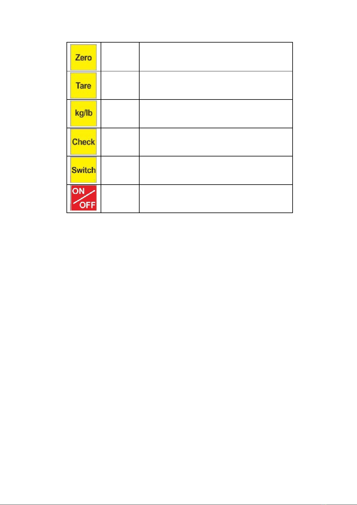
Keys function
keys
Key name
Key function
Print
1.Printing the weighing data as weighing.
2.Working with the switch button to get into the menu
of calibration.
Store
In accumulative weighing mode, to accumulate the
axle weight and print the weight data.
6
Zero
Zero the weight within tolerance
Tare
At G.W mode, get the tare weight. At N.W mode,
clear the tare, get the G.W
Kg/lb
Covert between kg and lb
convert
Check
Check and read the saved weight data to print.
Switch
Switch the weight between the pad weight and the
total weight.
Power
Press 2 seconds to power on or power off
on/off
3.2 Power on & off
Press the "on/off" key for 2 seconds in the shutdown state, and the indicator will start
automatically; Press the "on/off" key for 2 seconds when the indicator is powered on.
When the indicator is powered on, you can check whether there are abnormal strokes or
LCD status indications according to the display, and then enter the weighing state.
3.3 Zero operation
Within the tolerance, “Zero” key clear the weight on all weighing pads. When the
pads unstable or loading over zero range or on tare mode, indicator can’t ZERO and
show ERROR.
3.4 Tare operation
In normal weighing mode, press ”Tare” button to make the load be tare weight; In
accumulative weighing mode, press “Tare” button to preset the tare weight and press
“ print” button to confirm the tare weight. The lights on the keypad is showing. In Tare
mode, press “Tare” button to deduct the tare weight from the total weight and show the
net weight.
NOTE:Tare mode only show on the total weight display.
Autres manuels pour T903
1
Table des matières
Autres manuels Tufner Instrument de mesure


Manuels Instrument de mesure populaires d'autres marques


Endress+Hauser
Endress+Hauser Proline Promag 50 Caractéristiques techniques

Siemens
Siemens SITRANS F Coriolis FCT030 Manuel de la liste des pièces

KLINGER
KLINGER CMF V Series Manuel utilisateur

EXFO
EXFO FTB-2 Manuel d'exploitation et d'entretien

Keysight
Keysight M8290A Manuel utilisateur

ADTEK
ADTEK MW-5 Manuel utilisateur