Tube Technology Fusion HB70 Manuel utilisateur
First edition published March 2001
© Tube Technology UK 2001
PART No. hb70/M-01
FUSION HB70
~USERS MANUAL~
i
Printed in Great Britain
' Fusion ' & ' Tube Technology ' are Trade-
marks of Tube Technology UK
HYBRID INTEGRATED
AMPLIFIER

Introduction
Thank you for selecting the FUSION HB70 Amplifier from Tube
Technology.
Please read through this manual so you will know how to operate
your Fusion HB70 properly. After you have finished reading this
manual, please put it away in a safe place for future reference.
We have done our utmost in the design and build of the Fusion
HB70 to ensure you a low maintenance, trouble free amplifier
that will bring you many years of pleasure as an important part of
your hi-fi system.
Please do not forget to complete and return the enclosed
registration card.
We wish you many hours of musical enjoyment !
ii
Contents
1.
2.
3.
4.
5.
6.
7.
9.
10.
Getting Started
Unpacking the Fusion HB70 Amplifier
Mains Connection
Connecting the Fusion to a Household Mains Supply
Wiring a Mains Plug - UK
Audio Connection
Connecting the Fusion HB70
Operating your System
Controls & Remote Functions
Installation
Installing & Ventilation of your Amplifier
Burning in your Amplifier
Maintenance
Care and Cleaning of your Amplifier
Vacuum Tubes
Troubleshooting
Specifications
Guarantee
Claims under the Guarantee
4
5
5
6
7
9
9
10
10
11
12
13
Conventions This manual uses the following conventions;
Bold indicates emphasis or a minor heading.
Italic Bold refers to a sub heading of a chapter.
This symbol refers to Notes containing important information set off from the text.
THIS SYMBOL REFERS TO CAUTION MESSAGES AND PROCEDURES WHICH
IF NOT OBSERVED CAN LEAD TO DAMAGE OR INJURY
Contents - 3

Getting Started - 4
Getting
Started
This chapter contains information on;
Unpacking the Fusion HB70 Amplifier
Your Fusion HB70 is packed in "jiffy-cell" end-caps. Grip the unit from the middle and
simply pull it out of the box. Remove the end-caps and polythene bag.
The following items are included in the packaging of a Fusion CD Player;
1 x Fusion HB70 Amplifier
1 x Remote Control Handset & 2 x AAA Batteries
1 x IEC Mains Leads
1 x Users Manual
Unpacking
All packing should be retained. Equipment returned can only be
accepted in the original packaging.

This chapter contains information on;
Connecting the Fusion to a Household Mains Supply
Wiring a mains plug (UK)
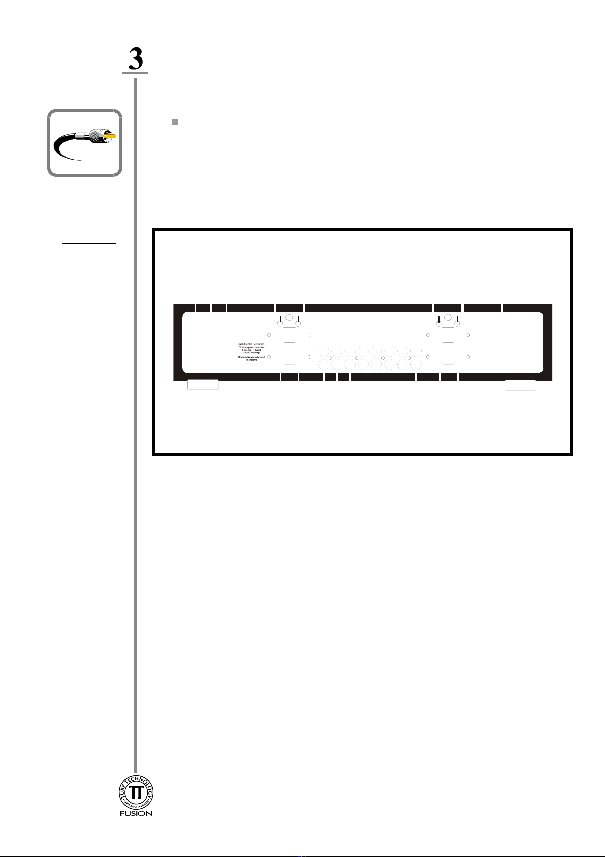
Your Fusion HB70 Amplifier plugs into the mains supply via the IEC socket located on the
back panel (see diagram 3). Connect your Amplifier to the wall socket using the IEC mains
lead supplied in the packaging. The Amplifier has been factory set to the correct mains
voltage for your country. The voltage setting is marked on the serial badge, located on the
rear panel. (See diagram 1). Check that this voltage complies with your local supply. Also
make sure that your mains outlet is able to deliver the required current for the equipment
plugged into it. The wattage rating is also marked on the serial badge.
Mains
Connection
DO NOT CONNECT/SWITCH-ON THE MAINS SUPPLY TO THE AMPLIFIER
BEFORE COMPLETING ALL OTHER CONNECTIONS. IF YOU ARE IN ANY
DOUBT REGARDING MAINS CONNECTIONS PLEASE DO NOT PROCEED ANY
FURTHER WITHOUT CONSULTING YOUR DEALER.
Mains
Connection
Export units for certain markets have a moulded mains plug fitted to comply with local
standards. If your mains supply lead does not have a plug fitted, the coloured wires should
be connected to the appropriate plug terminals in accordance with the following code.
Wire Colour Label on Plug
GREEN/YELLOW Eor EARTH or
BLUE Nor NEUTRAL or BLACK
BROWN Lor LIVE or RED
If your mains plug has a fuse, please fit a fuse with 13A rating.
If your Amplifier is not set correctly for the local supply or if you intend to move the
Amplifier to a location where the supply is at a different voltage, please contact your dealer.
Wiring a
Mains Plug
Mains Connection - 5
WARNING - THIS APPARATUS MUST BE EARTHED
Audio
Connection This chapter contains information on;
Connecting the Fusion HB70 Amplifier
Connect all Line-Level sources in any of the six inputs labelled (7) in the diagram
above. Connect your CD Player, Tape Deck, Tuner to the labelled inputs and any
other line-level sources such as mini-disc or AV outputs can be connected to
Aux1,Aux2 or Aux3.
If you have a Tape Deck or any other recording device connect its input to REC
OUT (6). The desired input selected on the front panel of of the HB70 can now be
recorded.
If you have other equipment such as a sub-woofer or slave amplifier which requires a
variable output from the Pre-Amp connect its input to PRE OUT (5).
Connect the Loudspeakers with either 4mm Banana Plugs or bare wire ends directly
in the binding posts (4) Right Channel & (8) Left Channel for a single wire system.
If Bi-Wiring connect the Bass R,L at (4) &(8), and the Treble R,L on (9) &(10).
Ensure that the Red or +lead of the speaker cable connects to the +on the
Amplifier and that the Black or -of the speaker lead connects to the -on the
amplifier.
Connecting the
Inputs
Connecting the
Outputs
Your Amplifier uses high quality connectors to ensure that maximum signal transfer is
possible, therefore ensure that all cables used for connection to the amplifier are terminated
with connectors of similar quality.
Connecting the
Loudspeakers
Audio Connection - 6
Diagram 1
This chapter contains information on;
Controls & Remote Functions
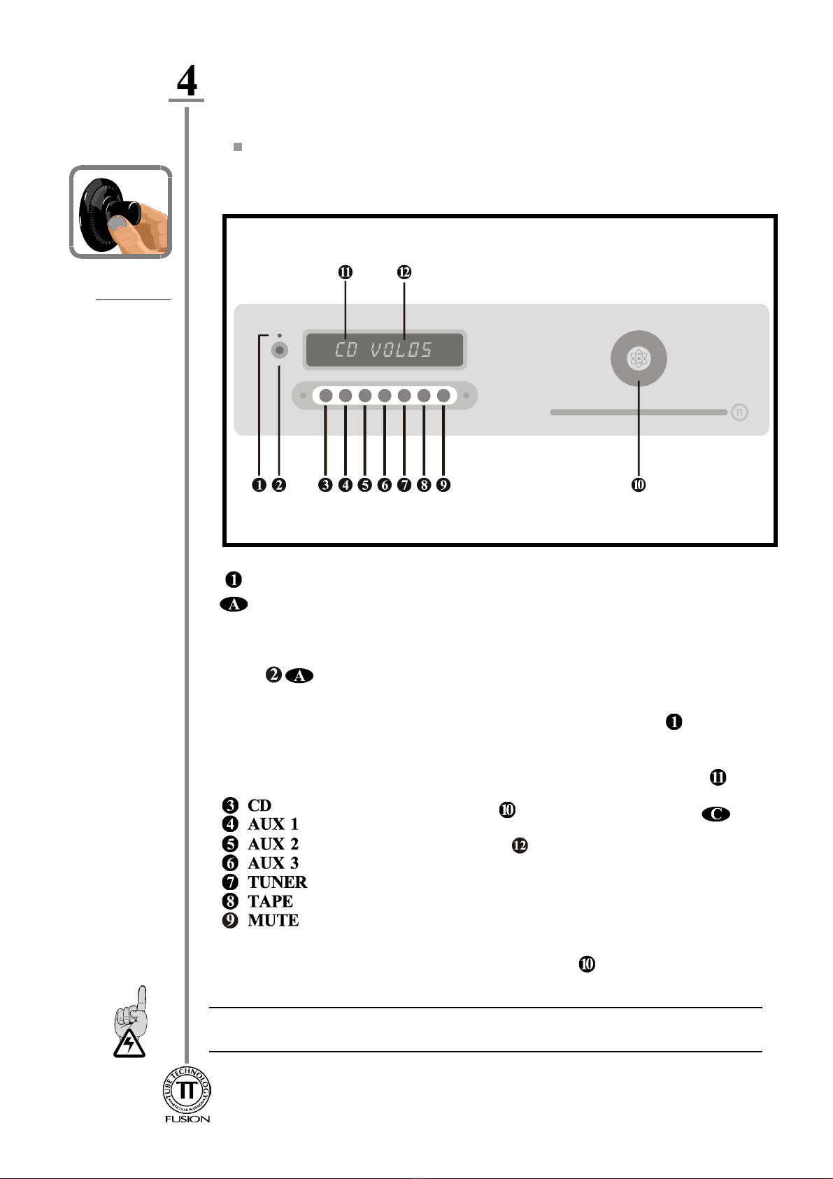
Diagram 2
Front Panel
Operating your System - 7
Operating
your System
Switch on the Fusion HB70 by pressing the rocker MASTER SWITCH(9) diagram 1 located
on the rear panel, to ON . The amplifier will display SLEEP in the display. Pressing the Power
Button will commence the power-up routine. The amplifier will remain in a MUTE
state, for 30 seconds until the internal vacuum tubes have reached operating temperature. The
Display will show WARM-UP followed by a count-down. Pressing this button again will
place the amplifier in Stand-By mode, using minimum power, the ST/BY led is illuminated
Select the desired source to be played by pressing either the remote control handset or
corresponding button on the front panel, the input selected illuminated in the display
Switching
ON & OFF
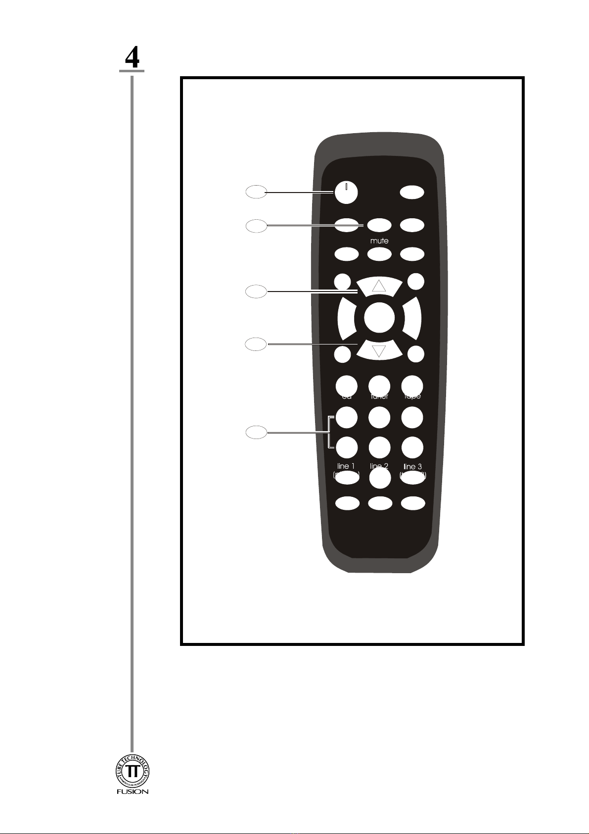
Controls &
Remote
Functions
Numbers in the circles relate to the Front Panel - Diagram 2
Letters in the ellipses relate to the Remote Control Handset - Diagram 3
Turn the Rotary Encoder on the Front Panel or press the
button on the remote to increase Volume, the volume setting is
illuminated on the display A Clockwise Turn on the control knob
increases the volume and an anti-clockwise turn decreases the volume.
If the knob is turned rapidly to a desired volume setting, a short delay
occurs before the required volume level is set.
The brightness level of the display can be set by pushing the control
knob in and turning it clockwise for increased brightness and
anti-clockwise for decreased brightness.
IT IS RECOMMENDED TO ALWAYS PLACE THE AMPLIFIER IN ST/BY / SLEEP
BEFORE SWITCHING OFF AT THE REAR.
Operating your System - 8
Diagram 3
Installation - 11
Installation
This chapter contains information on;
Installing & Ventilation of your Amplifier
Burning in your Amplifier
Installing &
Ventilation
Ensure that the Amplifier is placed in a stable location that is able to accept its weight, each
unit weighs 10 kilograms.
Isolated shelves and/or isolating feet under the unit helps prevent micro-vibrations (generated
in the room while playing music) from disturbing the internal vacuum tube structure, and
digital electronics, implementing the use of these will further enhance sound quality.
Dedicated racks are available for housing your tube equipment, contact your dealer or
Tube Technology for further information.
Do not locate the Amplifier close to radiators or any other heat source, this could increase
the operating temperature.
Do not locate the Amplifier too close to a turntable, as the cartridge could pick up hum from
the power transformer.
"Burning-In" is our generic term given to the basic 'running-in' of the Amplifier. You may
notice a slight 'electronic-smell' from your Amplifier during the first few days of operation.
This smell is usually caused by the heating of various surfaces on brand new electronic
components which takes some time to evaporate. This is quite normal and there is no need
for concern as your Amplifier has been extensively soak tested before leaving the factory.
This burning-in time continues with your use of the amplifier.
This process simply allows for new components like tubes, capacitors and resistors to settle
and 'sweeten' enhancing the Amplifiers sonic performance. An estimated 80 hours of
operation allows your Fusion this running-in period.
Burning-In
Anodised parts such as the front panel & Lid are best cleaned with a damp cloth then
buffed with a dry cloth. Stubborn 'greasy' marks in the grain can be removed with a tiny
amount of washing-up liquid worked into the grain and then carefully cleaned with a damp
cloth.
The Fusion utilises 2 x 6922/E88CC or 6DJ8 vacuum tubes in it's analogue input stage.
The life span of these devices is approx. 8000 operating hours after which time they should
be replaced, ensuring the unit is operating at it's maximum performance. If this time is
exceeded there is NO danger to the unit.
Maintenance
Care &
Cleaning
This chapter contains information on;
Care and Cleaning of your CD Player
Vacuum Tubes
Maintenance - 12
Vacuum
Tubes
Table des matières
Autres manuels Tube Technology Amplificateur


