Tronic TR10250 Manuel utilisateur

Residential ESS Battery Cabinet
TR10250 | TR20450 | TR30750| TR40950
Quick Guide
TRONIC ESS CO., LTD

1
Pr
o
duct Ov
e
rv
ie
w
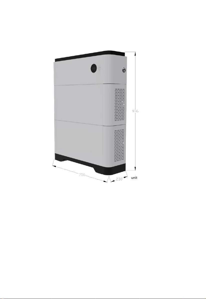
1.1 ESS Battery Cabinet Product Appearance
ESS Battery Cabinet is applicable to the grid-tied or off-grid systems. It
can store and release electric energy based on service requirements.
Note: The TR20450 ( 10 kWh) model is used as an example.
ESS Battery Cabinet consists of a power control module and battery expansion
modules. Each power control module is 5.12 kW, and can expanded to 4
power control modules. (total 20.48kWh).
Power control module
(1)Mounting handle (2)Disconnecting switch (3)Debugging port
(4)Power display (5)Start switch (6)Inverter COM port
(7) Inverter cascading terminals (8) Internal COM port
(9) Battery cascading terminals
Top Cover
Base
Battery expansion module
(5.12kWh)
Battery expansion module
(5.12kWh)
Power control module
DC Switch
Left View
9
2
Front View
Right View
8
7
6
5
4
1
3
1

Power control module
(1)Mounting handle (2)Internal COM port 1
(3)Battery cascading terminal(+) (4)Battery cascading terminal(-)
(5)Internal COM port 2
Product diagram
(1)Top cover (2)Protective cover (3)Power control module
(4)Battery expansion module (5)Bottom cover
1
2
3
2
4
2
4
5
2
2
2
Right View
Front View
2
3
4
1
5
1
Left View

1.2 ESS Battery Cabinet Model
TRONIC ESS has different electricity products to meet user’s needs, such
as TR10250、TR20450、TR30750、TR40950.
1.3 Technical data

1.4 System Schematic

2
Device Installation
2.1 Installation Requirements
2.1.1 Installation Environment
2.1.2 Installation Space
inverter
front≥1000mm
unit:mm
2.1.3 Mounting Hole Dimensions
unit:mm

2.2 Installation and fixation
1. Place the base in a horizontal position, then put the battery unit on the base.
(Note: pay attention to the red circle mark in the figure, the battery unit and the
base should be completely consistent to prevent dislocation).
2. Using a fixing piece to fix the battery unit with the base.
(Note: when fixing, the torque shall not exceed 1.2N. M to prevent equipment
damage.)

3. Place the remaining battery units and power control units respectively.
(Note: when fixing the component unit, the torque shall not exceed 1.2N. M
to prevent equipment damage. When fixing the wall, the torque shall not
exceed 1.2N. M; The power control unit is placed on the battery unit. The
legend is jk20450 product. There are two battery units, each 5kwh, the
battery unit parameters are the same, and the installation sequence is not
divided).
M6
5

3
Inte
rna
l
Electric
al
C
o
nn
ect
io
ns
o
f
the
Bat
t
e
ry
Note:
A. The internal connecting wires are packed in the box;
B. Before connecting cables, ensure that the switches of the devices are
turned off. Otherwise, high voltage electric shock and equipment
damage may be caused.
3.1 Connection of Battery Cable
The battery expansion modules in the ESS battery cabinet are
connected in series.
The top battery expansion module "+" is connected by
the power control module "battery cascading terminal
+", the top battery expansion module "-" is connected
to the next battery expansion module "+", and so on.
The lowest battery expansion module "-" is connected by the
"battery cascading terminal" of the power control module- .
3.2 Connection of Communication Cables
The ESS Battery Cabinet uses Daisy chain for internal
communication.
As shown in the figure, the battery expansion modules are
connected one by one.
The battery expansion module at the top is connected with the
power control module internal communication interface
the bottom battery expansion module’s internal COM port is
connected to a terminal resistance.
3.3 Connection of Internal Ground Cable
For the internal ground cable of the ESS Battery Cabinet,
connecting each component unit one by one as shown in right
picture.
-
+
-
+
Battery Cascading
Terminal -
Ground
Cable
Internal
Communication
Cable
Battery
cable
Battery Cascading
Terminal +
Terminal
Resistance
Ce manuel convient aux modèles suivants
3
Table des matières


