TriMark 500-1300 e-ASK Manuel utilisateur
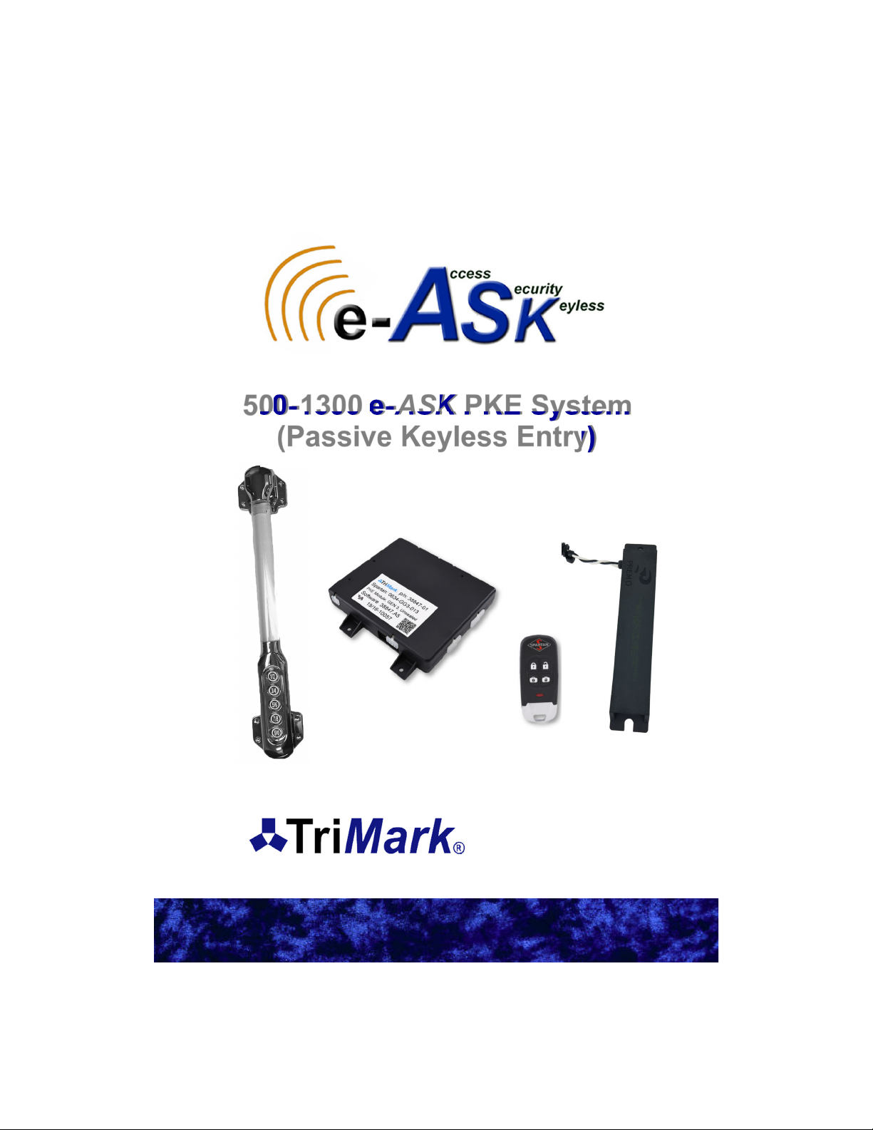
500-1300 e-ASK PKE System
(Passive Keyless Entry)
(UM31~ 500-1300)
38246 and 38847
500 Bailey Avenue
P.O. Box 350
New Hampton, Iowa 50659 U.S.A.
www.trimarkcorp.com

In the event that you have a question regarding the Passive Keyless Entry System,
please contact Spartan RV Customer Service at the following contacts before you
contact TriMark Corporation:
Spartan Recreational Vehicle Owner Support:
800.543.4277
(Option 1) Customer & Product Support/Chassis information
(Option 2) Owners Training Information
(Option 5) Factory Service & Repair Appointment
(Option 6) Retail, Non-warranty Parts
Table of Contents
Introduction .................................................................................. 4
General Component Overview ................................................... 4
e-Controller (38246-01 and 38847-01) ................................... 4
e-FOB (38245-01) ................................................................... 4
Lighted Grab Handle with Keypad (36444-03) ....................... 4
Antenna (36159-01) ................................................................ 5
Standard Operating Procedures—Section 1 ............................ 6
Push to Start ........................................................................... 6
Running ................................................................................... 6
Shutdown ................................................................................ 6
Locking (typical) ...................................................................... 6
Unlocking Entrance (typical) ................................................... 6
Alarm Functionality .................................................................. 6
Arming the Alarm .............................................................. 6
Feedback .......................................................................... 7
Disarming the Alarm ......................................................... 7
Cancelling the Alarm ........................................................ 7
Tripping the Alarm ............................................................ 7
Auto Locking ........................................................................... 7
Auto Lock / Unlock ............................................................ 7
e-FOB Operation and Features (38245-01)—Section 2 ............ 8
FOB Functionality .................................................................... 8
Pairing FOB ............................................................................. 9
Panic Mode ............................................................................. 9
Activating .......................................................................... 9
Deactivating ...................................................................... 9
e-ASK Fob Guidelines…………………………………………...10
Keypad Operation and Features (36444-03)—Section 3 .......... 11
Default Access Code ........................................................ 11
Default Authority Code ..................................................... 11
Standard Operation ................................................................. 11
Locking ............................................................................. 11
Unlock the Entrance Door ................................................ 11

Unlock All Doors ................................................................ 11
Unlock Bay/Cargo Doors ................................................... 11
Teaching Keypad New Authority / Access Codes ................... 12
Programming Authority Code ............................................ 12
Programming Access Code ............................................... 12
Keypad Wiring .......................................................................... 13
Module Operation/Features (38246-01/38847-01)—Section 4 .. 14
Module Connectors and Functions .......................................... 14
Connector Locations ......................................................... 15
J1—Main Chassis Connector 24-Pin ................................ 16
J2—Parking Break 10-Pin ................................................. 17
J3—External Relay Drivers 8-Pin ...................................... 17
J4—Relay Outputs 6-Pin ................................................... 17
J5—Relay Outputs 4-Pin ................................................... 18
J11—Push to Start PKE 12-Pin ........................................ 18
J13—Entry Door PKE 14-Pin ............................................ 19
Dip Switch Settings .................................................................. 19
Appendix A: Wiring Diagrams
Entry Door ................................................................................ 20
Bay/Compartment Doors ......................................................... 20
PKS .......................................................................................... 21
Keypad ..................................................................................... 21
Accessories (Inputs) ................................................................ 22
Accessories (Outputs) .............................................................. 22
Appendix B: Mounting e-ASK Components .............................. 23
General Mounting Guidelines .................................................. 23
I/O Module…………………………………………………….25
Chrome Keypad………………………………………………26
Appendix C: Acronyms ................................................................ 26
Appendix D: Error Codes ............................................................ 27
Appendix E: Troubleshooting ..................................................... 28
Appendix F: CAN Requirements ................................................. 31
Appendix G: Warranty ................................................................. 32
TriMark makes every attempt to assure that information contained in
the User Manual is correct and accurate; however, changes in design,
dimension and specifications may occur at any time and without notice.
Please verify the revision level of this manual (back page) by referring
to TriMark’s website under Product Code 500-1300.
Note: Product photos and illustrations may vary from your specific part
numbers.

Introduction
This manual provides the necessary information for the proper
installation and use of TriMark’s e-ASK system. The e-ASK comes with
the following components:
e-FOB: Keyless entry RF FOB transmitter with Passive keyless
LF PKS (Passive Keyless Start) ability
e-ASK I/O Module: The input/output processor with low
frequency (LF) and RF transceiver capabilities
Antennas: LF interior antennas for FOB section
Handle with Touchpad: A five button chrome handle. It allows
for locking and unlocking functions via a CAN network
This new generation of TriMark’s e-ASK not only maintains its previous
advantages for controlling door and accessory control, it also adds
value to the Original Equipment Manufacturer (OEM) and customer by
incorporating remote keyless entry, immobilization and keyless start
into a single package.
The FOBs have typical lock/unlock buttons that can be used up to 50
meters depending on architecture and location. For security reason, RF
signals are encrypted using randomly generated numbers. This is what
allows the system to start by pressing a button. The system uses the
LF/RF messaging to ensure an authorized FOB is within range inside
the vehicle. A combination of LF challenges and RF responses delivers
low power consumption for long battery life.
General Component Overview:
e-CONTROLLER (38246-01/38847-01)
Enables distributed functionality,
such as multiple door control and
ignition immobilization, via vehicle
multiplex communication
CAN network functionality with error
handling
Fault displaying LEDs
LF transceiver (FCC/IC compliant)
RF transceiver (FCC/IC compliant)
Programming port
Selectable visual/audible controls
4
38246-01/38847-01

e-FOB (38245-01)
Stylish 4-button PKE FOB
LF transceiver that can reach 1 meter though open
air and is FCC/IC/EU compliant
RF transceiver that can reach 100 meters though
open air and is FCC/IC/EU compliant
Control lock, unlock, lighting, alarm system, and
panic operations
High security using random number generators and
proprietary decryption algorithm between the FOB
and controller to prevent attacks/hacking
Lighted Grab Handle with Keypad (36444-03)
Entry assist handle incorporated TriMark’s e-ASK
keypad into a stylish combo for RV coaches, motor
homes and travel trailers
Lighted rod and lighted assist keypad for a more
enjoyable low visibility experience
Button presses with tactile, visual, and audio feedback
CAN network with error handling and communicates
with the TriMark e-Controller
Fault display both audio and visual
Water and dust resilient to outdoor environments
Antenna (36159-01)
Location identifying internal antenna for push to start
functionality
Potted construction ensures environmental protection
and durability performance—can be used in exterior or
interior locations 36444-03
36159-01
5
38245-01

Standard Operating Procedures — Section 1
Push to Start
Pressing the engine start button will begin the process of detecting a
FOB in range (J11P2 active). Our system will look in the area of the
driver. If the FOB is in range it will respond with a single blink. If the
FOB is authorized. Our system will tell the motor that it may start.
Running
Once running, the FOB is not required to keep the vehicle running.
Note: You can drive away without your FOB in the vehicle. You will not
be able to start the vehicle again without the FOB.
Shutdown
With your vehicle in park, a short press of the start/stop button will turn
off the vehicle.
Locking (typical)
Press and hold the Button 1 button on the keypad or press the lock
function on the FOB.
Unlocking Entrance (typical)
Type in the five digit code followed by the 1 button or press the unlock
function on the FOB.
Note: Programming new codes into your keypad can be found in
section Keypad Operation and Features (36444-03) - Section 3
under Teaching Keypad New Authority / Access Codes.
Alarm Functionality
Arming the Alarm:
Performing a “lock all” with the touchpad or the key FOB will attempt to
set the alarm.
The word “attempt” is used above because several conditions can block
the alarm from being armed:
Parking brake not set (in gear)
Pressing the button to start the vehicle
Any security inputs are in the active state
Any door ajar input are in the active state
6

Feedback:
If you activate the alarm from keypad, the system will send a
single pulse to the headlights.
If you activate the alarm from the FOB, the system will send a
single pulse to the headlights and horn/siren.
If you fail to activate the alarm the siren will sound 3 times.
Disarming the Alarm:
The alarm system will immediately be disarmed if one of the following
things occurs:
You start the engine
Any unlock signal
The vehicle is put into gear
Cancelling the Alarm:
Any of these conditions will cancel an active alarm:
The vehicle is put into gear
The engine is started
An unlock command of any door/compartment
The alarm timer expires
Tripping the Alarm:
After arming the alarm, if the security input (J1P13) or any of the door
ajar inputs are tripped, the alarm will activate. When active, the siren
will go off and the headlights will flash for one minute.
Auto Locking
Auto Lock / Unlock
The parking brake is monitored to utilize this auto locking feature:
Whenever the vehicle parking brake activates, a timer is started.
Seven seconds later a lock all sequence is done.
Whenever the vehicle parking brake activates, the entrance door
is unlocked.
Parking Brake Description
Engaged Active
The parking brake is active and the vehicle
cannot move. The vehicle is considered “not in
use”.
Disengaged Float
The vehicle will move if no other brakes are
applied. The vehicle is considered “in use”.
This is usually caused by putting the vehicle
into gear.
7

Unlock Entry
Unlock Cargo
Lock Cargo
Lock All
38245-01
e-FOB Operation and Features (38245) —
Section 2
FOB Functionality
Pressing a button on the FOB should cause the LED to flash multiple
times. The LED will also flash anytime it is located by an antenna. This
happens when you start your vehicle and the FOB search near the
drivers seat is initiated.
The FOB is powered by a standard 2032 3V battery.
Note: Typical use has 2 years without replacing the batteries. May be
subject to variation from OEM as the time the FOBs were created is not
the day the coach was sold.
Button Function
Lock All Locks all doors
Unlock Entry Unlocks entry doors
Lock Cargo Locks the cargo doors in the order of section A, B, C, D
Unlock Cargo Unlocks the cargo doors in the order of section A, B, C, D
8

Pairing FOB
You will need to have access to the module to pair FOBs. To
understand pin names and functions please reference Module
Operation and Features (38246-01/38847-01) — Section 4.
There may be a push button attached to J13P2, if it is not supplied,
short J13P2 (learn pin) to J11P1 (12Volt pin) when it says “push
button”.
Note: Programming new FOBs will unlearn any programmed FOBs
previously stored. You may learn up to 50 FOBs. Make sure you have
all the FOBs that you wish to program before starting this process.
1. Press the push button 3 times within 5 seconds (more than 3 is
acceptable)
a. The system will send a pulse to lock and unlock the entry
door
b. Two LEDs (red and green) located near the dip switches will
remain on as long as the controller is in learn mode
2. Press and release a button (any button) on each FOB
a. The system will send a pulse to lock and unlock the entry
door
3. Wait 10 seconds
a. Entry door unlocks and you exit FOB learn mode
Panic Mode
Activating
The Panic Mode sequence is activated by pressing and holding for 2
seconds the panic button on the FOB. During Panic Mode, siren and
headlight outputs are used to draw attention to the vehicle. Panic mode
cannot be used if the parking brake is not active (vehicle in gear).
Deactivating
Panic time of 60 seconds expires
Unlock command from the FOB
Unlock from the keypad
Vehicle engine turns over
Parking brake inactive (vehicle in gear)
9

The e-ASK fob is designed to use commonly available CR2032
batteries. Estimated end customer normal use should have an expected
life of 2 years for the fob battery. Variances across commercial battery
manufacturers and operating environment conditions will result in
deviations from the expected battery life. The following guidelines
should be followed to optimize fob battery life and system performance.
The e-ASK fobs are designed to operate in a low power or “sleep”
mode. The fobs electronics will “wake up” upon detection of a button
press or LF signal from the control module. The fob will return to “sleep”
mode once the event that woke it up is completed.
When a fob is in close proximity, 2-3 inches, from other vehicle control
units, cell phones or inductive cell phone charger pads, electrical
signals from these devices can prevent the fob from returning to “sleep”
mode and can reduce battery life. Additionally, when in close proximity
to these other electrical devices, their emitted electrical signals can
saturate the fobs internal receiving antennas and prevent the fob from
receiving proper LF signals.
It is recommended for optimal fob performance and battery life that a
distance of at least 5-6 inches minimum be maintained between fobs
and other such mentioned electronic devices.
Due to the chemical process inherent in batteries, the performance of
the e-ASK Fob will be degraded at extreme temperatures. Operating
temperature ranges will vary across batteries from different
manufactures. For commercially available CR2032 batteries the typical
operating temperatures ranges from –0C to +60C.
At cold temperature, the batteries chemical process is slowed down and
can result in reduce Fob range performance or an inoperative fob.
When the battery is returned to warmer temperatures, normal
performance will return. Extreme cold temperatures, below –20C, can
cause a battery to freeze and fail due to expansion of internal plastic
components. Simply replacing the battery will allow the fob to function
normally.
At extreme hot temperatures, the batteries chemical process is
accelerated. This will result in a reduced life expectance of the battery.
Normal Fob range performance can be expected at higher temperatures
as long as manufacture limits are not exceeded.
10
Autres manuels pour 500-1300 e-ASK
1
Table des matières
Autres manuels TriMark Démarreur à distance

TriMark
TriMark e-ASK UM06 Manuel utilisateur

TriMark
TriMark e-ASK Manuel utilisateur

TriMark
TriMark 500-1300 e-ASK Manuel utilisateur

TriMark
TriMark e-ASK UM27 Manuel utilisateur

TriMark
TriMark e-PAD Manuel utilisateur

TriMark
TriMark e-ASK UM 36 Manuel utilisateur

TriMark
TriMark e-FOB Manuel utilisateur

TriMark
TriMark e-ASK UM15 Manuel utilisateur

TriMark
TriMark e-ASK Manuel utilisateur

TriMark
TriMark e-ASK Manuel utilisateur


