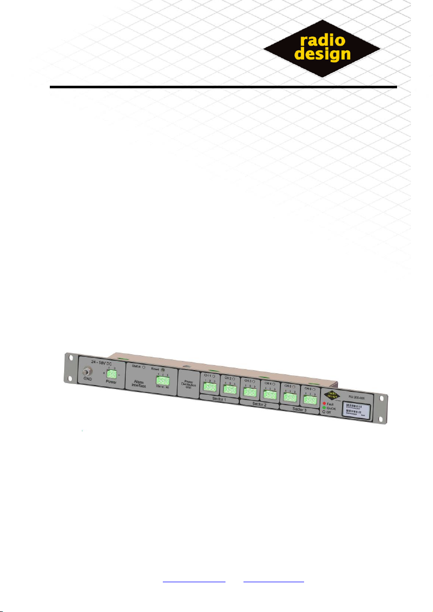
TRAC radio design RD300 PDU Guide de démarrage rapide
a TRAC company
a TRAC company
RD0300-01
Power Distribution Unit
Radio Design Ltd is a Company Registered In Scotland –No. 328828
Shipley Wharf, Wharf Street, Shipley, West Yorkshire, UK Tel: +44 (0) 8452 770125 Fax: +44 (0) 8452 770126
Company Proprietary and Confidential
99-438 Issue 05 Page 1 of 16
RD300 PDU
Installation
And
Operational manual

a TRAC company
99-438 Issue 05 Page 2 of 16
Installation
Tools Required
1 * 10mm open –ended spanner
1* medium flat bladed screw driver [8mm]
1*small flat bladed screw driver [3mm]
Mechanical Installation
19” Rack Mounting
The unit is primarily designed for 19” rack fitment, using the included
mounting screw set.
Un-Mounted
If no suitable mounting is available it is permissible to mount the unit on a
shelf, but this is not recommended.
This Symbol indicates that special attention should be
paid to the section in the manual and a user action
may be required.

a TRAC company
99-438 Issue 05 Page 3 of 16
Electrical Installation
It is strongly recommended that all connections are made to the PDU in
the following order:
1. Earth connection
2. Connect Bias-T [1 to 6]
3. Connect alarm interface.
4. Connect power.
Earth connection
The front panel of the PDU has a 6mm Earth stud provided to enable the
unit to be grounded to the installation ground point. Cabling used should
conform to local installation standards.

a TRAC company
99-438 Issue 05 Page 4 of 16
Bias-’T’ Connection
Each Bias-‘T’ should be connected to the PDU using the RD308 interface
cable.
Check the shorting link between pins 1 and 2 of the interface cable
PDU connector is not removed, as this will result in the channel not
being enabled.
Check The Connections to the BIAS-T are not reversed
Ensure that unused channel connections [for example in 2 sector
configurations] are left open; thereby ensuring they will not generate
alarms.
3
2
1
CH X
CNTRL
0V
+12V RD308 [ PDU to BIAS-T cable ]RD308 [ PDU to BIAS-T cable ]
PDU

a TRAC company
99-438 Issue 05 Page 5 of 16
Remote Alarm Interface [RAI]
The PDU provides a VOLT-Free Alarm interface.
Table 1 ALARM Relay
PDU State
COM –N/O
COM –N/C
PDU OFF
Open circuit
Short Circuit
PDU ON - Alarm
Open circuit
Short Circuit
PDU ON - No Alarms
Short Circuit
Open circuit
N/O = normally open contact
N/C = normally closed contact
N/O
N/C
COM
RAI
3
2
1
RD307 [ PDU ALARM cable ]
PDU
ALARM Relay shown in
the “alarm” state
The correct choice of connections [COM and N/O] or [COM and N/C] will
depend upon the alarm sense required.

a TRAC company
99-438 Issue 05 Page 6 of 16
Power
The PDU is powered from 48V dc using the provided cable RD306.
Terminal 1 of the PDU must be positive with respect to PIN 2,
Table 2 Power Connections shows the required connections for a positive
or negative supply option.
The PDU is protected against reverse polarity connections but if the
polarity is not correct the PDU will fail to function.
Table 2 Power Connections
Power
PIN 1
PIN 2
+ 48v supply
+ 48v
0V
- 48v Supply
0v
- 48v
2
1
Power
+
-RD306 [ PDU POWER cable ]
PDU

a TRAC company
99-438 Issue 05 Page 7 of 16
Connection Detail:

a TRAC company
99-438 Issue 05 Page 8 of 16
Operation Instructions
Power on
Once the unit has been fully installed with all required bias-‘T’s channels and the alarm interface has
been connected, power can be applied to the unit.
During the power on sequence all the front panel indicators should be seen to go through a power on
test [RED/GREEN/YELLOW]
ALL connected Bias-‘T’ channel s will now go through their start up sequence, with the respective
channel indicator going from yellow to green for all connected channels, if any indicators go RED this
indicated a channel fault.
The unit status indicator will be seen to be GREEN +short blink RED if there are no channels in a fault
condition. [See: Table 3 Status Indicator]
Momentarily press the reset switch after which the status light should be steady GREEN.
Channel Fault Conditions
A channel will be in a fault condition if the current drawn from the channel is outside the normal
operational current [i.e. the current draw is too high or too low].
When a channel first enters a fault state the controller will try to reset the channel three times. If the
fault will not clear then the channel will enter the FAULT state at which point the power is removed
from the affected channel and the remote alarm interface will indicate a FAULT mode. A faulty channel
is indicated by a RED channel indicator.
The controller will try to reset a faulty channel on an hourly basis; the remote alarm interface will
continue to will indicate a FAULT mode until all enabled channels are operating correctly.
Persistent State
Once a channel has been enabled, disconnecting the channel will result in a fault condition even if the
power to the PDU is cycled.
In order to disconnect a channel fully it is necessary to press the reset switch for more than 5
seconds [status indicator will turn YELLOW], then release, at which point the channel status
indicator will go OFF.

a TRAC company
99-438 Issue 05 Page 9 of 16
LED Indications
Table 3 Status Indicator
STATUS Indicator
Meaning
OFF
No Power to the PDU/ PDU Failure
GREEN
No Alarms
RED
Output channel in alarm, or NO channels enabled
GREEN+BLINK RED
No Alarms, and unit has been through power cycle
RED +BLINK GREEN
Output channel in alarm, or NO channels enabled and unit has
been through power cycle
YELLOW
This mode can only be reached by user intervention and
indicates that the RESET switch has been pressed for more than
5 seconds, thereby forcing a major reset, and clearing the
persistent channel configuration.
Table 4 Channel Indicator
CHANNEL Indicator
Meaning
OFF
Channel is not enabled
YELLOW
Channel starting
GREEN
Channel OK
RED
Channel Fault

a TRAC company
99-438 Issue 05 Page 10 of 16
Fault Finding
Table 5 Fault Diagnosis, may be used to diagnose common faults:
Table 5 Fault Diagnosis
Fault Condition
Possible Cause
Possible solution
Status Indicator OFF
No power to PDU
Apply power
Incorrect polarity of PDU power
Check polarity.
PDU Faulty
Try new unit
Status Indicator GREEN
but blinking RED
Normal state after power cycle
press reset to clear.
Status Indicator RED
Channel is in fault condition
Check each channel for fault indication.
Channel Indicator OFF,
but Bias-‘T’ connected
Link on connector between PINS
1 and 2 missing
Fit link between pins 1 and 2
Channel Indicator RED,
and BIAS-‘T’ connected.
Channel is in a fault condition
Press reset switch
Swap working channel with faulty
channel.
-If fault follows the BIAS-‘T’
the fault is in the BIAS-‘T’ or
cable, check wiring.
-If fault stays on the channel
PDU may be faulty.
Channel Indicator
RED, NO BIAS-‘T’
connected.
Channel was connected,
but has been
disconnected
Press reset switch for more
than 5 seconds [till status
indicator goes yellow]
Table des matières
Autres manuels TRAC Treuil

TRAC
TRAC Salt Water Series Manuel utilisateur

TRAC
TRAC Titan 450 T10240 Manuel utilisateur

TRAC
TRAC T10108-25 Manuel utilisateur

TRAC
TRAC T10102-35sw Salt Water Coastal 35 Series Manuel utilisateur

TRAC
TRAC Salt Water Series Manuel utilisateur

TRAC
TRAC T10219 Manuel utilisateur

TRAC
TRAC Angler 30 T10208-AD Manuel utilisateur

TRAC
TRAC Big Water 45 Manuel utilisateur

TRAC
TRAC T10109-35 Manuel utilisateur

TRAC
TRAC T10108-25 Manuel utilisateur


