Titan 50SPREAD Manuel utilisateur
50lb Walk-Behind Spreader
OWNER’S MANUAL
MPN: 50SPREAD; SKU: 890011
Titan Mfg and Dist, Inc.-3839
Forest Hill-Irene Rd. St#100
Memphis, TN 38125

2
2. Remove and identify loose parts from carton and bag.
1. HELPFUL HINTS:
READ THE DIRECTIONS BEFORE ASSEMBLY
WHEN ALL ELSE FAILS, READ THE DIRECTIONS AGAIN
If your spreader does not spread evenly, be sure the FRONT on the gear box points to
the front of the spreader. The impeller must turn clockwise. Reversing the gear box will
cause the impeller to turn counter clockwise. Clean the impeller plate after each use.
Fertilizer stuck on the impeller blades will cause uneven spreading.
Your spreader is designed to be pushed at three miles per hour, which is a brisk walking
speed. Slower or faster speeds will change the spread patterns. Wet fertilizer will also
change the spread pattern and flow rate. Clean your spreader thoroughly after each
use. Wash between the shut off plate and bottom of the hopper.
Gears are permanently lubricated at the factory. Do not open the gear box or dirt may
enter.
#20 Wheel Assembly
Frame
2PCS
#23 Upper Handle
2PCS
#26 Handle Shaft
1PC
#30 Frame
1PC
#25 Control Rod A
1PC
#45 Cross
Brace
1PC
#49
Rain
Cover
#42 Impeller
1PC
#36 Wheel
1PC #16 Hopper
1PC
#39 Gear Box &
Axle Assembly
1PC
#19 Pivot &
Bracket
1PC
#4 Gauge &
Lever
Assembly
1PC #31 Frame Brace
1PC
#14 Screen
1PC
3
ASSEMBLY INSTRUCTION
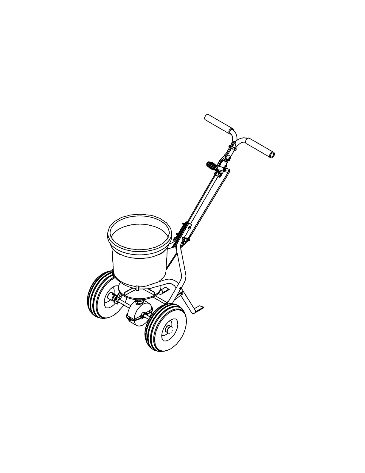
1. Turn Hopper (#16) upside down
and attach Frame (#30) using four
screws ST6.3 x 40 (#43).
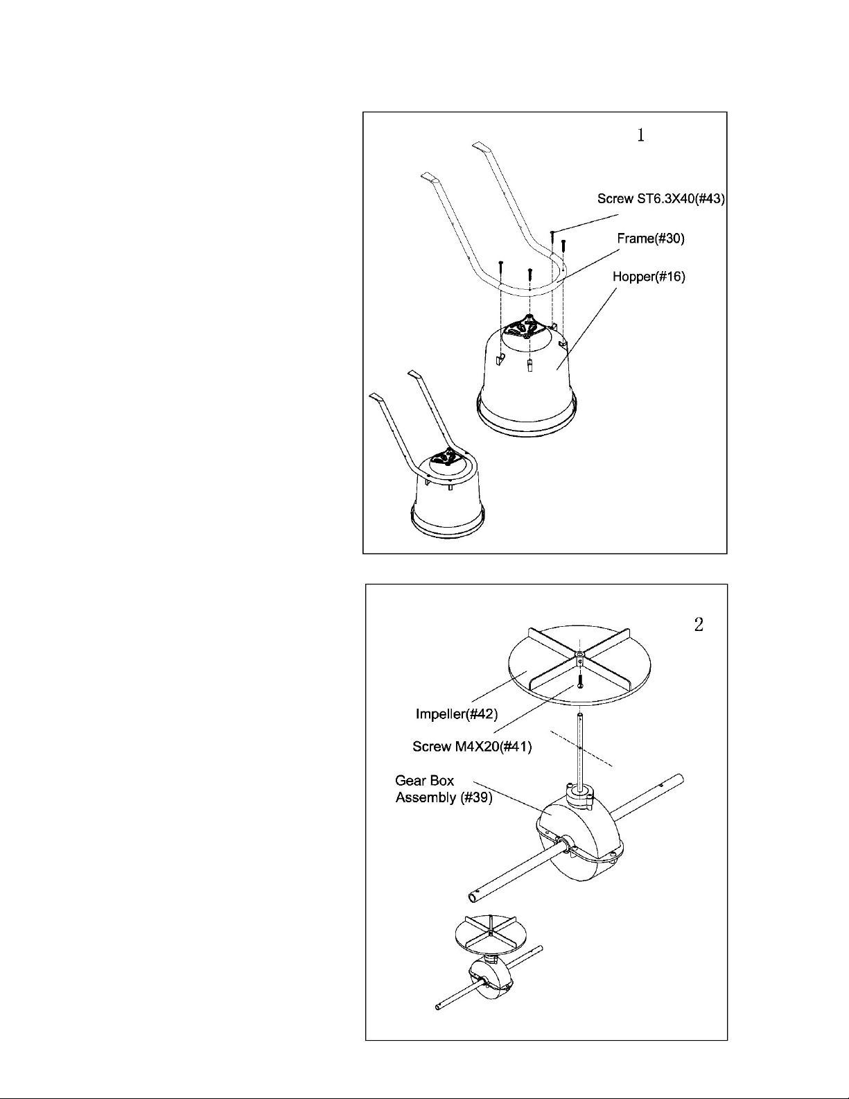
2.a) Slide the Impeller (#42) onto the
spindle of the Gear Box Assembly
(#39).
b) Insert Screw M4 x20 (#41)
through the Impeller and the top of
the gear box spindle.

4
3.a) Find the two Wheel Assembly
Frames (#20).
b) Insert M6 x 60 bolt (#32) through
the right hand Wheel Assembly
Frame (#20) and into the Hopper
Frame Assembly (#30). Secure with
Lock Nut M6 (#24). Repeat on left
side.
NOTE: The nuts and bolts do not
have to be completely tightened yet.
4. a)
Attach one end of each Frame Brace
(#31) to the outside of the Hopper Frame
Assembly (#30) using bolt M6 x 35 (#33)
and M6 lock nut (#24).
b) Push a M6 x35 bolt (#33) through
the first hole above the axle in right hand
Wheel Assembly Frame (#20). Pass bolt
through the Frame Brace (#31) and into
the end of the Cross Brace (#45).
Repeat with the left side.
NOTE: The nuts and bolts do not have
to be completely tightened yet.

5
5.Slip Inner Axle Bushing (#37) onto the right side of the axle, pushing the Inner Axle Bushing
into the Outer Axle Bushing until tight. Attach Wheel (#36) to the right side of the axle by inserting
a M5 x 45 bolt (#47) and fastening with Lock Nut M5 (#44). Attach Axle End Cap (#35) by tapping
with a wooden or rubber mallet.
b) Slip Inner Axle Bushing (#37) onto the left side of the axle, pushing the Inner Axle Bushing into
the Outer Axle Bushing until tight. Push the Wheel onto the axle. Insert nylon washers(#52)to
the two sides of the wheel, then insert Flat Washer Ø16 (#34) and attach Axle End Cap (#35) by
tapping with a wooden or rubber mallet. NOTE: The nuts and bolts do not have to be completely
tightened yet.
Note: Insert the Inner axle
bushing into the outer axle
bushing and make sure they
are tight.
6.
Insert Handle Shaft (#26) between the top ends
of the Wheel Assembly Frames (#20). Pass two
Bolts M6 x 45 (#11) through Wheel Assembly
Frames and Handle Shaft. Slip Pivot and Bracket
Assembly (#19) onto protruding bolt ends. Fasten
with Lock Nuts M6 (#24). Pivot and Bracket
Assembly should be on the right side of the
handle when standing behind the spreader.
GO BACK AND TIGHTEN ALL NUTS AND
BOLTS ASSEMBLED SO FAR. DO NOT OVER
TIGHTEN.
NOTE: The handle can be higher or lower
depending on the user’s preference. Before
installing the gauge, upper handles and handle
shaft, decide which of the three positions will be
most comfortable for the operator. If the middle or
upper positions are chosen, use a handle spacer
in the hole nearest to the handle grips.
5
6

6
7. a) Insert Bolts M6 x 45 (#11) through the
Upper Left Handle (#23), then through the
Handle Spacer (#1) and Upper Handle on
the Right side, screw with Flat Washer Ø 6
(#48) and Lock Nut M6 (#24). Slide Gauge
and Lever Assembly (#4) onto the bolts and
fasten with Lock Nut M6(#24).
b) Tighten lock nuts securely.
8. a) Push the Adjustable Handle (#6, #7) to
the lowest position.
b) Insert the upper end of the Control Rod
(#25) into the hole at the end of the
Adjustable Handle (#6, #7).
c)Take lower nut (#21) off the bottom end
of the Control Rod (#25) and insert rod into
the hole in the Pivot and Bracket Assembly
(#19).
d)Screw nut back into place.

7
9. Slip the threaded end of Adjustable
Connecting Rod (#46) into the Shut Off Plate
(#27) with a Flat Washer Ø6(#48), then fasten
with Flat Washer Ø6(#48)and Lock Nut M6
(#24).
10. a) The three large holes at the bottom of the hopper should match the three holes in the
adjustable plate. If they match, do nothing. If they do not match, push the handle down to the
lowest position and adjust the positions of the two nuts on the threaded control bar until the three
holes match up. If the holes are not properly aligned, the hopper will not close completely.
b) To operate the spreader, push the handle up to the top position. Adjust the wing nut as
needed to regulate the flow of material passing through the spreader.
c) Insert R Pin (#17) into the hole at the top of the axle spindle at the bottom of the Hopper
(#16) as shown. Make sure impeller is turning in the right direction as indicated by the arrow.
d)Place Screen (#14) into the Hopper (#16).

8

9
DRAWING

10
PARTS LIST
Ref# Drawing No. Description Qty
1 N570-00012-000 Handle Spacer 1
2 9114-06025-DG Carriage Bolt M6x25 1
3 9315-08000-DG Teeth Washer Ø8 1
4 N570-10000-000 Gauge & Lever Assembly 1
5 N570-00001-000 Adjust Handle Pole 1
6 N570-00014-000 Adjust Handle A 1
7 N570-00015-000 Adjust Handle B 1
8 9199-04018-DG Screw ST4.2x18 1
9 N510-00016-000 Spacer 1
10 N510-00019-000 Wing Nut M6 1
11 9101-06045-DG Hex Bolt M6x45 5
12 C130-00004-000 Nylon Washer 1
13 9302-06000-DG Big Flat Washer Ø6 1
14 N570-00016-000 Screen 1
15 N570-00009-000 Handle Cover 2
16 N570-00013-000 Hopper 1
17 N578-00001-000 R Pin 1
18 N570-00019-000 Hopper Bushing 1
19 N570-30000-000 Pivot & Bracket Assembly 1
20 N570-00007-000 Wheel Assembly Frame 2
21 9201-06000-DG Hex Nut M6 2
22 T680-00003-000 End Cover 2
23 N570-00006-000 Upper Handle 2
24 9206-06000-DG Lock Nut M6 12
25 N570-00003-000 Control Rod A 1
26 N570-00005-000 Handle Shaft 1
27 N510-00023-000 Shut off plate 1
28 9302-04000-DG Big Flat Washer Ø4 3
29 9199-04012-DG Screw ST4.2x12 3
30 N570-00008-000 Frame 1
31 N570-00010-000 Frame Brace 2
32 9101-06060-DG Hex Bolt M6X60 2
33 9101-06035-DG Hex Bolt M6X35 4
34 9301-16000-DG Flat Washer Ø16 1
35 N511-40000-000 End Cap 2
36 N570-00020-000 Pneumatic Wheel 2
37 N570-00018-000 Inner Axle Bushing 2
38 N570-00011-000 Outer Axle Bushing 2
Table des matières
Autres manuels Titan Épandeur


Manuels Épandeur populaires d'autres marques


Fisher
Fisher POLY-CASTER 78601 Manuel utilisateur

TurfEx
TurfEx RS7200 Manuel du propriétaire

Ferris
Ferris Pathfinder Series Manuel utilisateur

Fayat Group
Fayat Group DYNAPAC S100 Guide de dépannage

Art's-Way Manufacturing
Art's-Way Manufacturing X700 Manuel d'installation et d'exploitation

EASTMAN
EASTMAN CR 500 Manuel utilisateur


