Tigo TSS-50-US Manuel utilisateur

1 | Page
Tigo Energy, Inc. | www.tigoenergy.com | support@tigoenergy.com
Tigo Energy Intelligence
Automatic Transfer Switch Installation and
Operation Manual
002-00088-00 | 10/22/2021

2 | Page
Tigo Energy, Inc. | www.tigoenergy.com | support@tigoenergy.com
Disclaimer
DISCLAIMER OF WARRANTIES AND LIMITATION OF LIABILITY
The information, recommendations, descriptions, and safety disclosures in this document are
based on Tigo Energy, Inc.’s (“Tigo”) experience and judgment and may not cover all
contingencies. If further information is required, a Tigo sales office should be consulted. Sale of
the product shown in this document is subject to the terms and conditions outlined in the Tigo
warranty or other contractual agreement between Tigo and the purchaser.
THERE ARE NO UNDERSTANDINGS, AGREEMENTS, WARRANTIES, EXPRESSED OR IMPLIED,
INCLUDING WARRANTIES OF FITNESS FOR A PARTICULAR PURPOSE OR MERCHANTABILITY,
OTHER THAN THOSE SPECIFICALLY SET OUT IN ANY EXISTING CONTRACT BETWEEN THE
PARTIES. ANY SUCH CONTRACT STATES THE ENTIRE OBLIGATION OF TIGO. THE CONTENTS
OF THIS DOCUMENT SHALL NOT BECOME PART OF, OR MODIFY ANY CONTRACT BETWEEN,
THE PARTIES.
In no event will Tigo be responsible to the purchaser or user in contract, in tort (including
negligence), strict liability or otherwise for any special, indirect, incidental or consequential
damage or loss whatsoever, including but not limited to injury to persons, damage or loss of
use of property, equipment or power systems, cost of capital, loss of power, additional
expenses in the use of existing power facilities, or claims against the purchaser or user by its
customers resulting from the use of the information, recommendations and descriptions
contained herein. The information contained in this document is subject to change without
notice.

3 | Page
Tigo Energy, Inc. | www.tigoenergy.com | support@tigoenergy.com
Contents
Disclaimer...................................................................................................................................................... 2
Contents ........................................................................................................................................................ 3
Safety Symbols .............................................................................................................................................. 5
Safety Information ........................................................................................................................................ 6
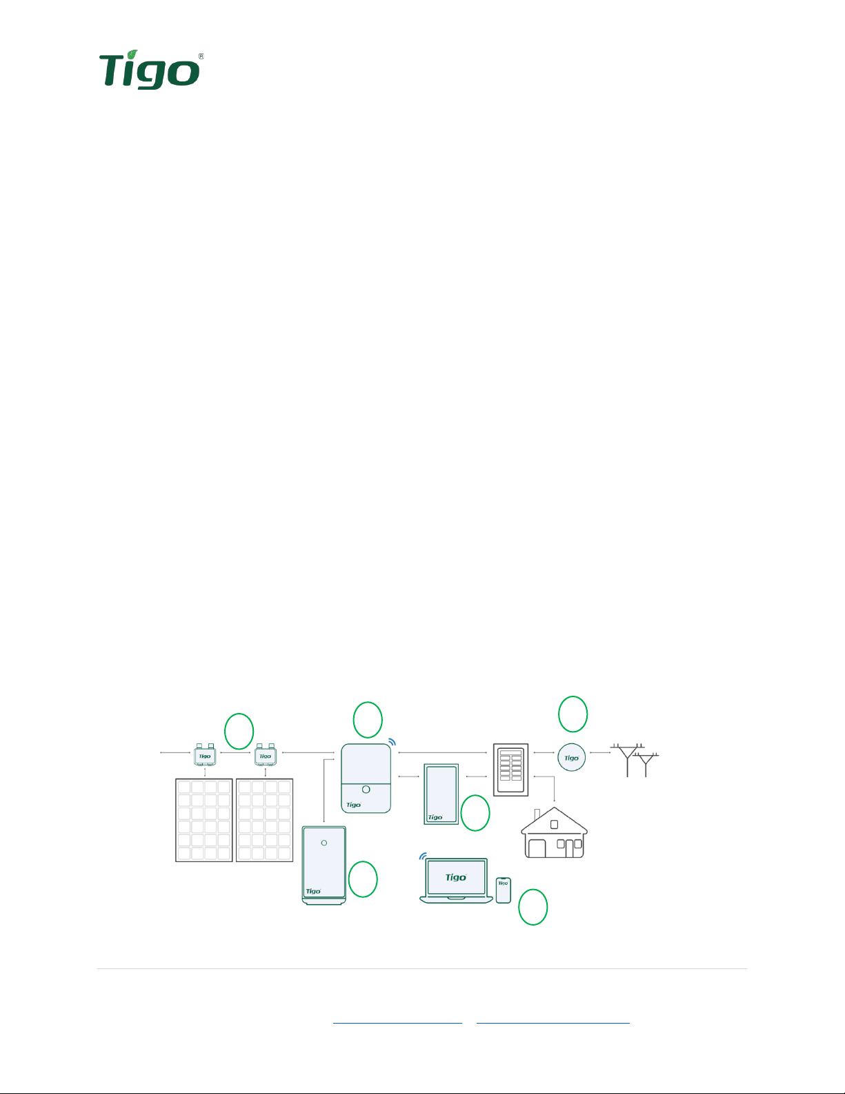
EI Residential Solution Overview .................................................................................................................. 7
The Energy Intelligence Residential Solution ............................................................................................ 7
Transportation and Storage ...................................................................................................................... 8
Understanding this Document .................................................................................................................. 8
Pre-Installation .............................................................................................................................................. 8
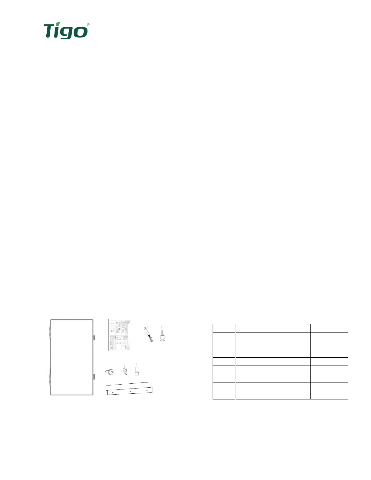
EI ATS Package Contents ........................................................................................................................... 8
Tools & Items Needed for Installation ...................................................................................................... 9
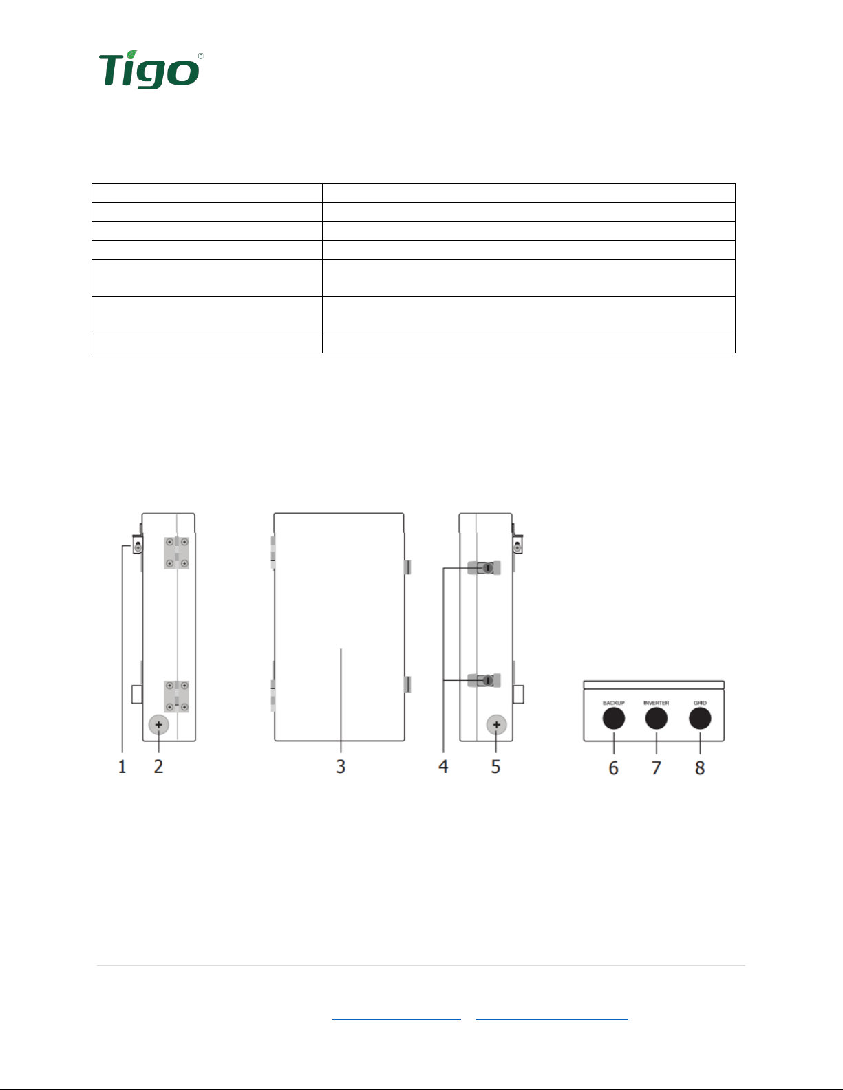
EI ATS Overview ........................................................................................................................................ 9
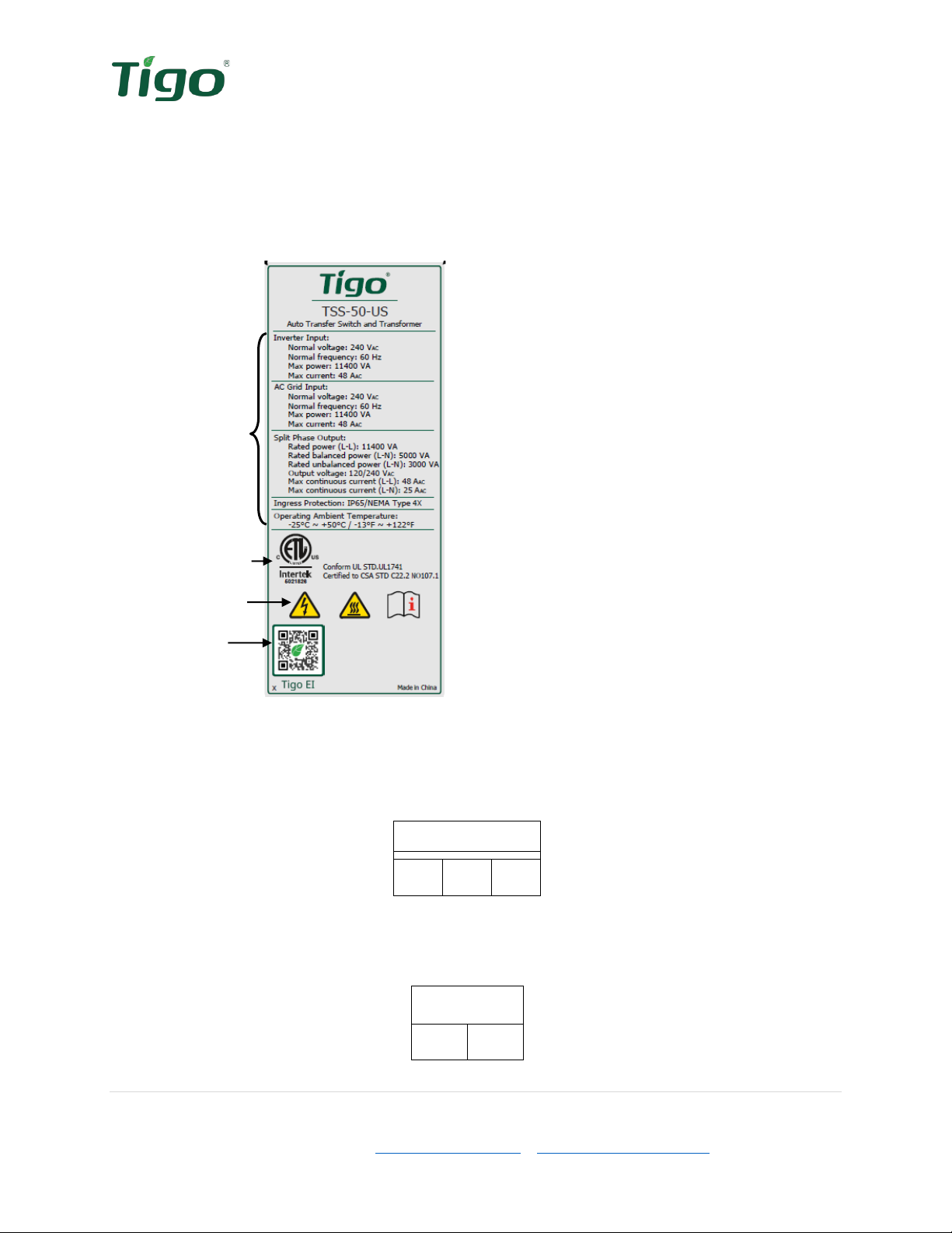
EI ATS Labels ........................................................................................................................................... 10
EI ATS Weight and Dimensions ............................................................................................................... 11
Installation .................................................................................................................................................. 12
Installation requirements ....................................................................................................................... 12
Mounting the EI ATS ............................................................................................................................... 13
Wiring the ATS ............................................................................................................................................ 14
Wire schedule and preparation .............................................................................................................. 14
Inverter connections ............................................................................................................................... 15
Grid connections ..................................................................................................................................... 16
Output connections ................................................................................................................................ 17
Commissioning ............................................................................................................................................ 18
Pre-power Check ..................................................................................................................................... 18
Torque Table ........................................................................................................................................... 18
Powering on the EI Solution .................................................................................................................... 19
After Installation ......................................................................................................................................... 19
Cleaning and Care ................................................................................................................................... 19
Maintenance ........................................................................................................................................... 19

4 | Page
Tigo Energy, Inc. | www.tigoenergy.com | support@tigoenergy.com
Troubleshooting ...................................................................................................................................... 20
Your Tigo Customer Support contact ...................................................................................................... 20
Decommissioning ........................................................................................................................................ 22
Packing the ATS ....................................................................................................................................... 22
Storing the EI ATS .................................................................................................................................... 22
Disposing of the ATS ............................................................................................................................... 22
Warranty ..................................................................................................................................................... 22
Specifications .............................................................................................................................................. 23

5 | Page
Tigo Energy, Inc. | www.tigoenergy.com | support@tigoenergy.com
Safety Symbols
The following safety symbols are used in this Installation and Operations manual. Please review
these symbols and their meanings before installing or operating the system.
Symbol
Explanation
WARNING indicates a hazardous situation which, if not avoided, could
result in serious injury or loss of life.
AVERTISSEMENT indique une situation dangereuse qui, si elle n'est
pas évitée, pourrait entraîner la mort ou des blessures graves.
CAUTION indicates a hazardous situation which, if not avoided, could
result in minor or moderate injury and damage of the product.
ATTENTION indique une situation dangereuse qui, si elle n'est pas
évitée, pourrait entraîner des blessures mineures ou modérées.
NOTE is used to address additional information about the section’s
subject matter.
AVIS est utilisé pour traiter des pratiques non liées aux blessures
corporelles.
On the ATS enclosure:
Symbol
Explanation
Risk of electrical shock
Risque d'électrocution
Risk of burn injuries
Risque de brûlures
Observe the operating instructions
Respectez les instructions de service

6 | Page
Tigo Energy, Inc. | www.tigoenergy.com | support@tigoenergy.com
Safety Information
Save these instructions.
Warning!
Read all instructions in this manual to reduce risk of injury, damage, and loss
of life.
The equipment detailed in this document are to be installed and maintained by
qualified personnel only.
This product could expose the user to chemicals known to the State of
California to cause cancer. For more information refer to
www.P65Warnings.ca.gov.
Caution!
This product must operate within the technical specifications of the datasheet.
Damage caused by failure to follow the contents of the EI ATS Installation &
Operation Manual is not covered by the warranty.
Note
The ATS is NEMA 4X rated. Unused conduit openings must be properly sealed
and all connecting conduit requires the use of appropriate fittings for the
application.
Use only copper conductors, solid or stranded. Never use fine stranded
conductors. All conductors must have a minimum temperature rating of 75°C.

7 | Page
Tigo Energy, Inc. | www.tigoenergy.com | support@tigoenergy.com
EI Residential Solution Overview
The Tigo Energy Intelligence (EI) Automatic Transfer Switch (ATS) is a self-acting switch which
acts to safely isolate the utility conductors and switch to the backup power source during a grid
outage. The ATS is a vital component in any grid-tied, storage backup system and a required
component of the EI Residential Solution when the EI Battery is included.
The Energy Intelligence Residential Solution
The EI Residential Solution includes the following components:
1. EI Inverter – The TSI-7.6K-US and TSI-11.4K-US inverters may be installed as grid-
tied only or as an energy storage system when paired with the EI Battery. The inverter
converts the PV array’s DC energy to AC for use in the building and when paired with an
EI Battery, acts as the battery management unit.
2. TS4 – Tigo’s MLPE, the TS4-A-F provides module-level rapid shutdown. The TS4-A-O
provides module-level monitoring, rapid shutdown, and best-in-class module-level
optimization with Tigo’s patented Predictive IV.
3. EI Battery (optional) – The LFP battery is designed for use specifically with the EI
Inverter. Up to four battery enclosures may be installed with the EI Inverters.
4. EI ATS (optional / required when batteries are used) – The EI ATS is an automatic
transfer switch which switches the home loads from grid + Solar/battery usage to
solar/battery usage only when the grid goes down. This is a required component to any
energy storage system when connected to the utility grid as it prevents the potential for
dangerous backfeed on the utility’s conductors.
5. Energy Meter – (optional / required when batteries are used) – The energy meter
monitors the import and export of energy into the home’s electrical system. This allows
the inverter to determine when and how much energy is required from the battery to
serve connected loads.
6. Energy Intelligence – Accessible through the web or mobile app, the EI Platform
provides visibility into system and module performance. The EI mobile app is also used
for commissioning the EI Residential Solution.
Figure 1 EI System Diagram
2
1
3
4
5
6

8 | Page
Tigo Energy, Inc. | www.tigoenergy.com | support@tigoenergy.com
Transportation and Storage
When possible, transport the ATS in the original packaging, facing up and do not expose to
inclement weather or unnecessary shocks and vibrations. If the original packaging cannot be
used, a box of similar size, without damage, and can accommodate the weight of the ATS. Take
precaution to ensure the packaging is fully closed and reasonably weather tight.
To store the ATS, select a dry environment with ambient temperatures of -13°F to 122°F (-25°C
– 50°C).
Understanding this Document
This manual includes installation references to three separate components of the complete
Energy Intelligence Residential Solution: inverter, battery, and ATS. Each of these components
(and more) are necessary for the proper operation of the EI Battery system.
Installation of the equipment can take place concurrently, although the EI Inverter is the hub of
all equipment in this system. Where a workstream can split off from the main efforts of ATS
installation, a QR code will be provided directing to the appropriate product’s documentation.
Pre-Installation
When receiving delivery of the EI ATS, examine the packaging for damage. If the packaging
appears to have damage through the box and into the contents, refuse delivery and notify the
vendor immediately. If damage appears external only, open the box and inspect for any product
damage and/or missing parts.
EI ATS Package Contents
Open the package and inspect the contents. The following components should be included. If
anything is missing, please contact the vendor immediately.
Figure 2 Package contents
Installation
A B C D
E F G
H
Table 1 Package list
Item
Description
Quantity
A
ATS
1
B
Quick Stary Guide
1
C
Sleeve anchor
3
D
Keys
2
E
Safety-lock screws
2
F
O-type terminal
3
G
Wire ferrules
8
H
Mounting bracket
1

9 | Page
Tigo Energy, Inc. | www.tigoenergy.com | support@tigoenergy.com
Tools & Items Needed for Installation
Table 2 Required Tools
Item
Needed for:
3/16” (5mm) Philips screwdriver
Removing/replacing covers, terminating conductors
Pencil
Marking drill holes
Level
Mounting the equipment
Drill & 8mm drill bit*
Drilling pilot holes for mounting. *Bit size will depend on
the mounting surface material and anchor sizes required.
Wire cutter/crimping tool
Crimping wire ferrules, O-type terminal and wire
preparation
Rubber mallet/hammer
Making sleeve anchors flush with wall
EI ATS Overview
Left side
Front
Right side
Bottom
Figure 3 ATS Enclosure Overview
1) Mounting bracket
2) 1-1/4” knockout
3) Front door
4) Door locks
5) 1-1/4” knockout
6) 1” backup load knockout
7) 1” inverter knockout
8) 1” grid knockout

10 | Page
Tigo Energy, Inc. | www.tigoenergy.com | support@tigoenergy.com
EI ATS Labels
EI ATS labels provide the technical specifications of the product as well as important safety
information. Additional information is available on these and other labels which will help with
the commissioning and installation of the EI ATS.
ATS Specifications
Model Number
Figure 4 Specifications label
Specifications
Certifications
Safety/Info icons
Tigo EI App
There are three labels on the inside of the ATS to help identify the correct termination points for
the conductors. The left side is dedicated to the AC output to the essential load panel.
Output
L1
N
L2
Figure 5 Essential load output label
The center terminals and label are dedicated to the EI Inverter’s AC input. This allows the EI
Residential Solution to power the essential loads in the event of a grid outage.
INV
L1
L2
Figure 6 Inverter input label
Autres manuels pour TSS-50-US
1
Table des matières
Autres manuels Tigo Changer


