Thwaites Mach 443 Instructions de montage

Tier II: Issue 4
T0473
Mach 443, Mach 444, Mach 474,
Mach 475
Operator’s
Instruction
Manual
3 - 4.5 Tonne (Hydrostatic)
Mach 475 - 3 Tonne Hi-SwivelMach 474 - 3.5 Tonne Powerswivel

Introduction
Safety Symbols
• Attention!
• Be alert!
• Your safety is involved!
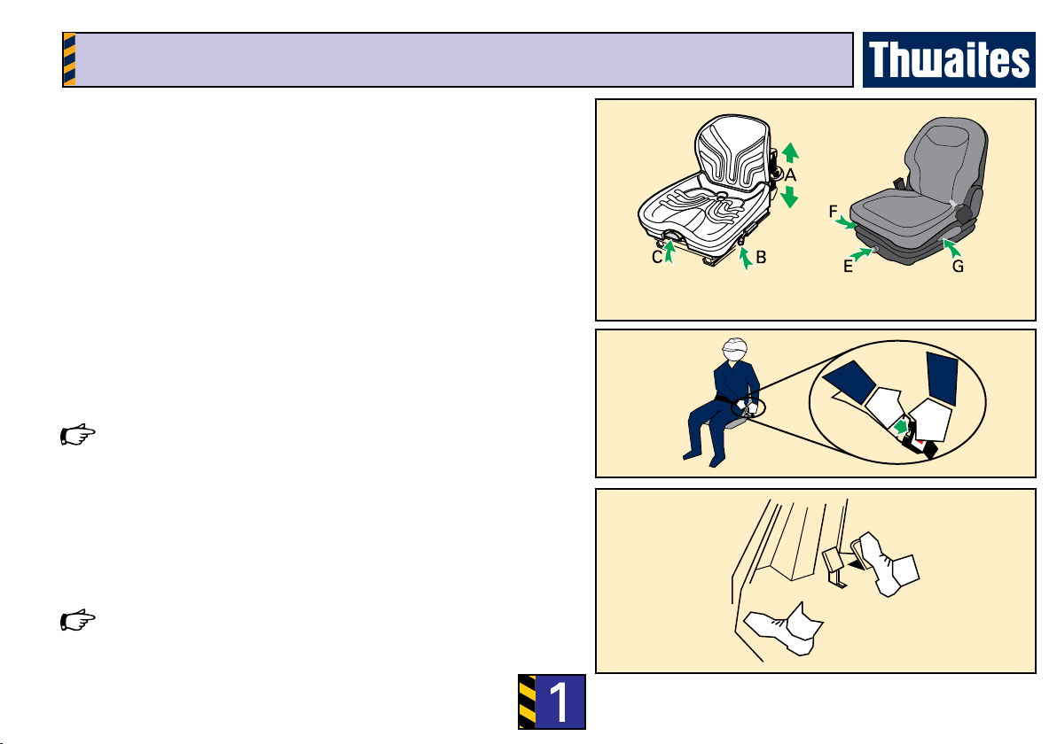
• Correct action • Incorrect action/procedure
which should NOT be carried
out
CAUTION
WARNING
DANGER
Signal words:
Signal words are used on the machine and within this manual to identify levels of hazard seriousness:
Thwaites Limited puts Safety First
It is the policy of Thwaites Limited to promote safety in the
operation of its machines and to create a general awareness of
site safety and safe working practices for the operators of its
machines.
This Operator’s Instruction Manual is intended for both new
and experienced machine operators. It should remain with
the machine at all times. All operators should be aware of its
location and contents.
It is important that all operators are fully trained and familiar
with the machine and that they have read and understood the
information contained within this book before they attempt
to operate in the site conditions for which the machine was
designed.
This book details practices and operations which Thwaites
Limited recommends. DO NOT operate this machine in ways
other than those detailed within this book.
This machine is designed for customary construction site
operations, and the transportation of bulk materials commonly
carried on such sites; that is their ‘intended use’. Under certain
controlled conditions the dumper may be used for towing
wheeled loads.
Due to the varied nature of the operation of site dumpers and
the absence of an agreed test standard, any gures quoted
by Thwaites in relation to vibration values and exposure are
for reference purposes only. It is the responsibility of the
employer to assess vibration exposure based on the actual site
conditions, and operating practices, at the point of use.
Hand Arm Vibration - The daily exposure Action/Limit Values
of between 2.5 - 5.0m/s2 (A8) are unlikely to be exceeded in an
eight-hour reference period.
Whole Body Vibration - The daily exposure can only be
accurately determined at the point of use. This exposure must
be managed in respect of the Action/Limit Values of 0.5 and
1.15 m/s2 (A8) respectively.
Employers should not rely solely on published vibration
gures when undertaking risk assessments. Depending on the
site conditions, cycle times may need to be adjusted in order
to reduce operator exposure levels.
Vibration values based on typical duty cycles are available
on request from Thwaites. These may be used for reference
purposes only.

1
Complete Checks in Section Before Starting The Engine
1 Contact your Thwaites dealer in case of further
questions
2 Learn to operate this machine
3 Ensure you are t to operate
4 Wear correct safety clothing and ensure that safety
equipment is available
Before operating this machine
Distributor
Read this manual

1
Complete Checks in Section Before Starting The Engine
Walk Around The Machine
Visually check the machine
1 Are the chassis lock and the skip lock disengaged?
2 Are the controls, crush zone and hydraulic rams
clean, and clear of debris?
3 Is the Roll-Over Protective frame (ROPS frame)
secure, fully upright and undamaged?
4 Is the seatbelt anchorage secure and serviceable?
5 Are the covers and mudguards secure?
6 Are the hoses free from uid leaks?
7 Are all safety decals legible?
8 Are the tyres free of cuts or splits?
9 Are all bolts tight and in position?
10 Are the steering wheel and the steering column
undamaged?
11 Have the daily maintenance tasks been
performed? (See rear cover)
Report all faults immediately.
Before operating this machine
DO NOT OPERATE THE MACHINE UNTIL
ALL FAULTS HAVE BEEN RECTIFIED.

1
Complete Checks in Section Before Starting The Engine
Mount the machine and check the controls
1 Use the grabrails and foot steps provided to
manoevre into seating position. Face the machine
at all times when mounting and dismounting
2 Is the engine cover secure and locked?
3 Adjust the seat position for comfort and easy
access to controls
4 Fasten the seatbelt. Adjust accordingly for safety
and comfort
5 Is the hand brake ON?
6 Set the transmission to neutral
7 Does the foot brake feel rm?
8 Do not operate the machine without understanding
all its controls as described in the following pages
WARNING
Seatbelt MUST BE WORN when operating machines
tted with a ROPS frame.
Before operating this machine

1
Complete Checks in Section Before Starting The Engine
Control locations & functions
1 Steering wheel.
2 Direction lever -
forward = left turn - back = right turn.
3 Lights - twist 1 = sidelights ON - twist 2 =
Dipped headlights ON
4 Up = ash. Down = main beam
5 Hazard warning light switch
6 Beacon switch*
7 Foot brake pedal/inching
8 Throttle pedal
9 Hand brake lever
10 Engine oil pressure warning light
11 Water temperature warning light
12 Headlamp main beam pilot light
13 Direction indicator pilot light
14 Heat/start pilot light
15 Battery charging warning light
16 Horn push
17 Skip-tip and Skip-rotate lever
17a Skip-raise lever (Hi-Swivel only)
18 Circuit breakers (push to reset)
19 Warning buzzer
20 Ignition switch
21 Forward/Reverse/High/Low Speed Lever (FNR
lever)
22 Maxi fuse (under engine cover)
CB1 Fuel/direction solenoids
CB2 Instrumentation/warning
CB3 Lights
CB4 Flash
CB5 L/H sidelights
CB6 R/H sidelights
Layout of controls

1
Complete Checks in Section Before Starting The Engine
7
8
Control Functions – in depth
Seatbelt (if tted)
• Adjust length of belt when seated on machine
• Press buckle blade into buckle lock
• Pull belt webbing through buckle blade to remove slack
Seatbelt should not be worn loose. It should pass comfortably across the
hips and not the abdomen.
Throttle pedal – right foot
• Apply pressure to increase speed
• Release pressure from the pedal to reduce speed
Foot brake pedal+inching pedal – right foot
• Push down on the pedal to slow/stop the machine.
Use left foot when inching is required.
Push down while pressing throttle pedal (8) with right foot and release to
move machine.
Seat adjustment
Type 1:
A – Push down to set driver weight (seat empty)
Push fully down and release to reset (seat empty)
B – Lift to slide seat assembly forwards/backwards
C – Lift to slide cushion forward and set backrest
Type 2:
E – Turn knob to set driver weight
F – Lift to slide seat assembly forwards/backwards
G – Lift handle to adjust backrest Type 1 Type 2

1
Complete Checks in Section Before Starting The Engine
Hand brake lever – right hand
When the machine is stationary (or in an emergency):
• Pull up to apply
• Pull catch and lower to release
An audible warning device is fitted to your machine. This will sound when
the hand brake is engaged and the engine is running.
FNR/High and low speed lever – left hand
• Push forwards to travel in a forward direction
• Lever centred = neutral.
• Pull back to travel in a reverse direction
Twist lever anti-clockwise (2) for HIGH speed travel
Twist lever clockwise (1) for LOW speed travel
Opening and closing the engine cover
• Insert ignition key and turn anti-clockwise to unlock
• Pull handle to release and raise cover
• Lower cover, secure and lock before driving
Control Functions – in depth

1
Complete Checks in Section Before Starting The Engine
Steering wheel – both hands
• Turn the wheel clockwise to turn machine to right
• Turn the wheel anti-clockwise to turn machine to left
Ensure the non-steering hand is on the engine cover grabrail when using the
spinner knob for low-speed single-handed steering.
Control Functions – in depth
Skip-Rotate lever (Powerswivel and Hi-Swivel models) – left hand
• Tip skip 100 mm (4”) to disengage pivot centring lock
Rotate skip, fully lowered to centre to automatically engage centring lock.
• Push lever to the right to rotate skip to right
• Push lever to the left to rotate skip to left
• An increased engine speed will reduce cycle times
Movement of the skip is disabled if the steering wheel is moved (priority
steering).
Skip-raise lever (Hi-Swivel model) – left hand
• push forward to raise skip
• push backwards to lower skip

1
Complete Checks in Section Before Starting The Engine
Lowering and raising the folding ROPS frame
• Remove linch pins and withdraw frame lock pins
• Lower frame and insert lock pins and linch pins in new position
• Reverse the procedure to raise the frame
• Ensure all pins are secure before driving
Beacon stowage
• Unplug and remove beacon
• Secure beacon on bracket provided beneath bonnet
Battery isolator (Beneath engine cover)
• Turn key anti-clockwise to isolate the battery power supply
Control Functions – in depth
Skip-tip lever lock (if tted)
• Place yoke over tipping lever and secure with linch pin to lock
• Fold back the yoke and secure using linch pin when not in use
Ce manuel convient aux modèles suivants
3
Table des matières
Autres manuels Thwaites Tracteur


