I. 4
Description of Model 1818AO
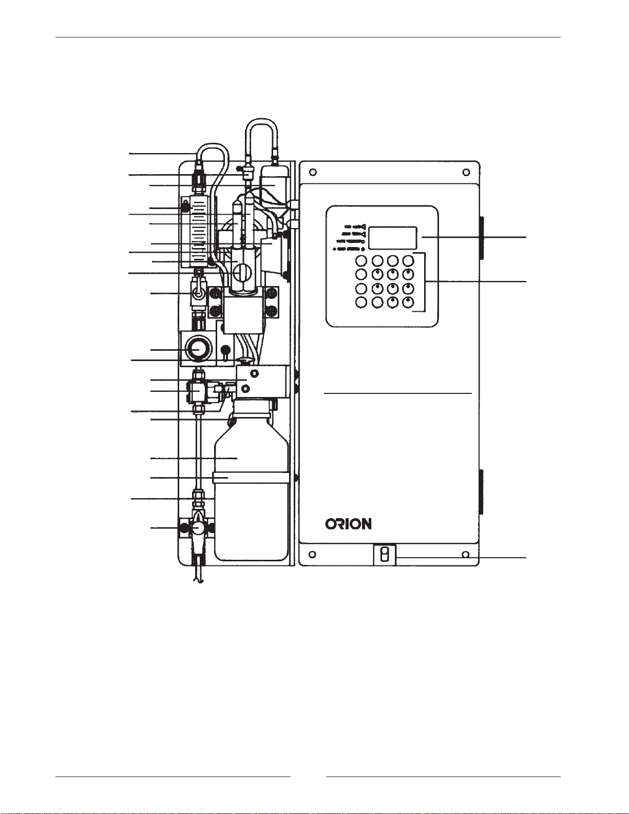
NOTE: Numbers in the description
refer to Figure 3.
Sample Inlet Valve (1) - Accepts the sample stream
via 1/4 inch NPTF connector. The customer must
supply the sample with a pressure between 8 and
100 psig, and a sample flow rate to the analyzer of
50 mL/min. minimum.
Bypass Filter Assembly (2) - 60 micron stainless
steel filter traps particulate matter in sample stream.
Pressure Regulator (3) - Adjusts flow on incoming
sample stream.
Flow Valve (4) - Used to turn off flow to flow cell.
Flow Meter (5) - Measures sample flow rate.
40 mL/min. nominal flow is required through the
analyzer.
Flow Restrictor Tubing (6) - Maintains steady
sample flow rate in conjunction with pressure regulator.
Pressurized Electrolyte Reservoir (7) - Provides a
constant flow of electrolyte solution through reference
electrode for maximum stability.
Reference Electrode (8) - Provides a constant refer-
ence potential and completes the measurement circuit.
Must be placed in right hand side of flow cell.
Iodide Electrode (9) - Senses iodide ions in sample
stream and produces an electrical potential dependent
on sample oxygen scavenger. Must be placed in left
hand side of flow cell.
ATC Probe (10) - Measures sample temperature
and inputs data to microprocessor for automatic
temperature compensation (ATC).
Reagent Mixing Loop (11) - Mixes iodine reagent with
oxygen scavenger in sample to form iodide, measured
by iodide-sensing electrode.
Flow Cell (12) - Contains reference electrode,
sensing electrode, ATC probe and sample measure-
ment reservoir.
Thumbscrew (13) - Supports the reagent diffusion
bottle.
Fluid Connector Block (14) - Connects reagent diffu-
sion bottle to sample stream and flow cell assembly.
Reagent Diffusion Bottle (15) - Acidifies and adds
iodine to the sample by means of passive diffusion.
LED Display (16) - Provides digital readouts of
concentration, temperature, millivolts and error codes.
Keypad (17) - Consists of five mode keys, four prompt
indicator lights, two scroll keys and one key for enter-
ing data. Mode and error indicators are also incorpo-
rated on keypad.
On/Off Switch (18) - Controls all power to the
electronics.
Drain (19) - Atmospheric drain prevents back pressure
on reference electrode.
Standard Injection Port (20) - Allows connection of
dynamic calibrator tubing to fluid connector block
during two-point calibration.
Bypass Valve (21) - Used to throttle flow in bypass
system.
Check Valve (22) - Prevents backflow of electrolyte
from pressurized reservoir.
Air Pump (23) - Provides air to pressurize the
electrolyte reservoir.
Bottle Clamp Band (24) - Holds reagent diffusion
bottle securely in place.