Copyright TheMagicTouch, Germany 2020
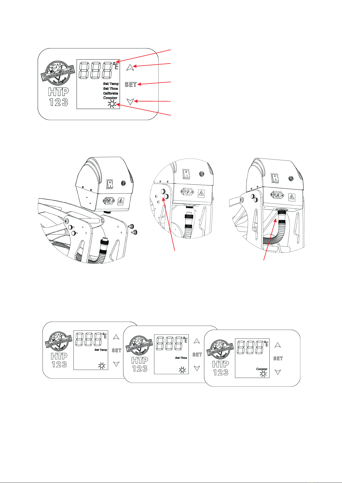
Control Panel Legend
LCD Display Set Temperature when lit
Up/+ Button
Down/- Button
Mode Selection Button
Set Time when lit Set Counter when lit
Controller Assembly
1. Insert Controller between
the Frame
2. Insert and tighten the
Hand Screws 3. Attach Heat Platen
Cable and tighten
the Screw Ring
Attach the Power Cable and switch the machine on. The Controller LCD should illuminate.
Adjusting Temperature, Time, Counter and Pressure
Press Set Button > ‘Set Temp’ will be lit > Select Temperature with the Up or Down Button >
Press Set Button again > ‘Set Time’ will be lit > Select Time with the Up or Down Button >
Press Set Button again > ‘Counter’ will be lit > Use the Down Button to re-set Counter to 1.
Press the Set Button again to return to StandBy/Idle. If you don’t need to make changes
just press the Set Button again to skip the Mode. At the end all Mode Indicators must be off
to return to StandBy/Idle.
To adjust the Pressure turn Pressure Knob clockwise to increase the pressure and counter-
clockwise to decrease. High pressure would be the point where you just still can close and
lock the press.
Warm-up when moving
C/F Temperature Range Indicator
Copyright TheMagicTouch, Germany 2020
Switch between C and F Temperature Calibration
Press the Set and the Up Button together
and hold for 3 Seconds to switch between
the C and F temperature range. The selected
will be shown by the C/F Temp Indicator.
Press the Set and the Down Button together
for 3 Seconds to enter the Calibration Mode.
“Calibrate” will be lit. Use Up or Down Button
to adjust the Value. Press Set button to quit.
Explosion View and Parts List
No. Material No. Name Qty
1 J.03.07.0002 Silicon pad SP-16.5*16.5-9-G 1
2 J.02.02.0033 Lower platen LP-16.5*16.5-C-S 1
3 J.03.06.0053 Handle JZN43 1
4 J.04.06.0004 Heat insulation sheet 2
5 J.03.05.0123 Ramlock female part GH-111 1
6 J.03.05.0126 Ramlock male part GH-114 1
7 J.03.05.0122 Ramlock handle GH-1131 1
8 J.03.05.0125 Ramlock locking set GH-113 1
9 J.03.05.0124 Ramlock base GH-112 1
10 J.03.06.0064 Spring washer 15*10*0.3 1
11 J.03.06.0063 Flat washer 16*10*1 1
12 J.03.05.0392 Ramlock screw GH-24-B 1
No. Material No. Name Qty
13 J.03.05.0139 Lower platen base B GCT-03B 1
14 J.03.05.0144 Bearing base GCT-02 4
15 J.02.05.0008 Axostyle B GCT-05B 2
16 J.03.05.0143 Holding block B GCT-04B 1
17 J.03.03.0008 O-shape washer WSH-02 4
18 J.03.05.0145 Axostyle holding block GCT-01 2
19 J.03.05.0136 Holding block B GC1-17 3
20 J.03.05.0137 Machine foot base GC1-02 2
21 J.03.03.0037 Rubber foot XD2512-148 2
22 J.03.05.0135 Machine body B GC1-01B 2
23 J.03.03.0029 Washer for gas spring 25*φ15 TB-17 2
24 J.03.06.0048 Gas spring 18-80-270N 2
25 J.02.05.0002 Threaded pin 13-164 GC1-18 2
26 J.03.03.0062 washer 20-13-39.5 GC1-11 2
27 J.02.05.0002 Threaded pin 13-164 GC1-18 2
28 J.03.03.0066 washer 20-13-12.75 GC1-10 4
29 J.03.05.0078 Aluminium sleeve 14-10-44 GC1-09A 1
30 J.03.05.0078 Aluminium sleeve 14-10-44 GC1-09A 1
32 J.03.05.0138 Gas spring arm link B GC1-24B-Y 2
33 J.03.05.0078 Aluminium sleeve 14-10-44 GC1-09A 2


