Texas Instruments TMP116EVM Manuel utilisateur

1
SNOU145A–June 2017–Revised August 2017
Submit Documentation Feedback Copyright © 2017, Texas Instruments Incorporated
TMP116EVM User's Guide
All trademarks are the property of their respective owners.
User's Guide
SNOU145A–June 2017–Revised August 2017
TMP116EVM User's Guide
The TMP116 devices are a family of high-precision digital temperature sensors with integrated EEPROM.
The TMP116 family provides up to ±0.1°C accuracy over the 20°C to 42°C range, and 0.2°C accuracy
over the 0°C to 85°C range with 16-bit resolution. The TMP116EVM evaluation module (EVM) provides
the user a simple way to get started with TMP116 family. The EVM features a perforation that allows the
temperature sensor to be placed away from the MSP430 for remote temperature measurements.

www.ti.com
2SNOU145A–June 2017–Revised August 2017
Submit Documentation Feedback
Copyright © 2017, Texas Instruments Incorporated
TMP116EVM User's Guide
Contents
1 Overview...................................................................................................................... 3
2 EVM Kit Contents............................................................................................................ 3
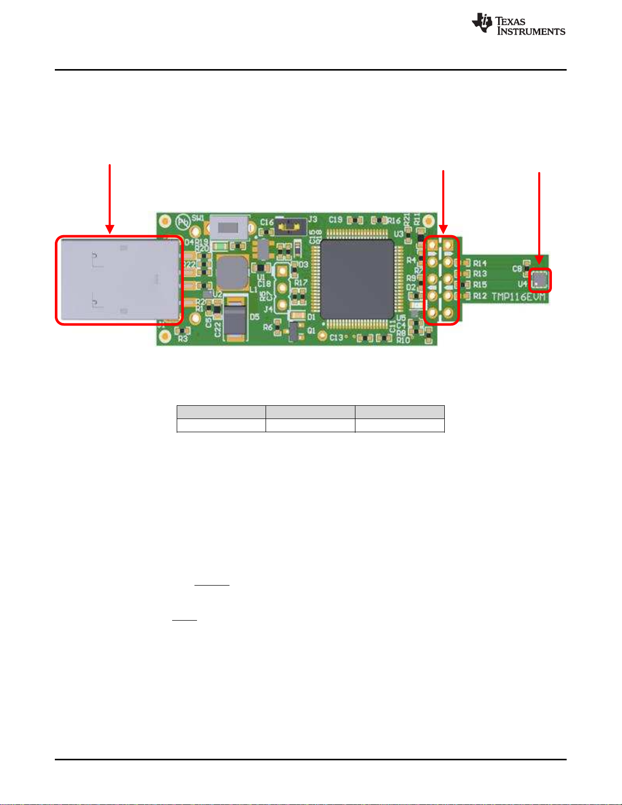
3 Board Connectors and Components...................................................................................... 4
4 Software Installation......................................................................................................... 6
5 Upgrading the Firmware................................................................................................... 10
6 TMP116EVM Setup and Operation...................................................................................... 14
7 Board Layout................................................................................................................ 20
8 Schematic and Bill of Materials........................................................................................... 22
List of Figures
1 TMP116EVM Evaluation Board............................................................................................ 4
2 TMP116EVM Welcome..................................................................................................... 6
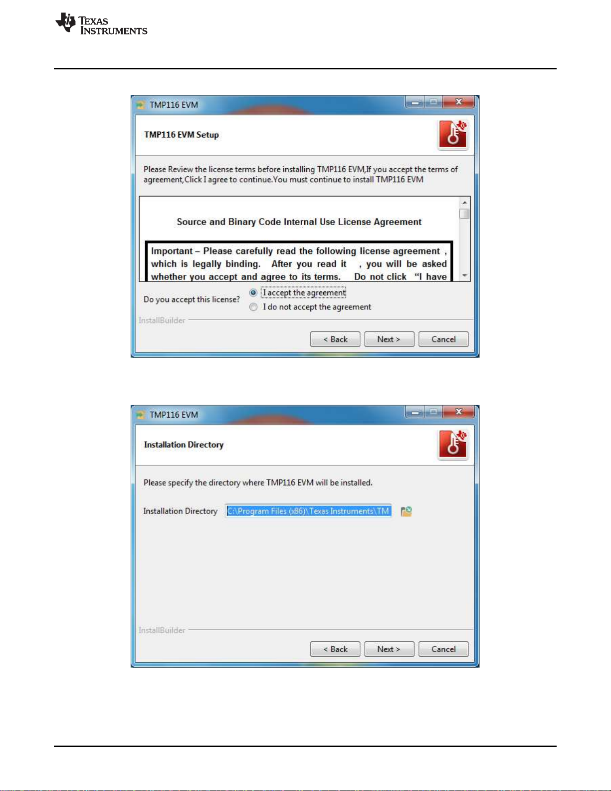
3 TMP116EVM License Agreement......................................................................................... 7
4 TMP116EVM Installation Directory........................................................................................ 7
5 TMP116EVM Select Components......................................................................................... 8
6 Proxy Configuration ......................................................................................................... 8
7 TMP116EVM Installation Finish ........................................................................................... 9
8 TMP116EVM Connection Diagram ...................................................................................... 10
9 Startup - Splash Screen................................................................................................... 10
10 TMP116EVM GUI.......................................................................................................... 11
11 Firmware Update Confirmation........................................................................................... 11
12 Firmware Update........................................................................................................... 12
13 Firmware Upgrade Successfully ......................................................................................... 12
14 Update Firmware Failed................................................................................................... 13
15 Confirmation of USB-to-I2C Converter Driver Installation ............................................................ 14
16 Default Configuration ...................................................................................................... 14
17 TMP116EVM Default Tab................................................................................................. 15
18 Registers Tab............................................................................................................... 17
19 Configuration Tab .......................................................................................................... 18
20 TMP116 Setup.............................................................................................................. 19
21 Top Assembly Layer....................................................................................................... 20
22 Top Layer Routing ......................................................................................................... 20
23 Power Layer Routing ...................................................................................................... 20
24 Ground Layer Routing..................................................................................................... 21
25 Bottom Layer Routing ..................................................................................................... 21
26 Bottom Assembly Layer................................................................................................... 21
27 TMP116EVM Schematic .................................................................................................. 22
List of Tables
1 EVM Kit Contents............................................................................................................ 3
2 Device and Package Configurations ...................................................................................... 4
3 I2C Slave Addresses........................................................................................................ 5
4 TMP116EVM Bill of Materials............................................................................................. 23

www.ti.com
Overview
3
SNOU145A–June 2017–Revised August 2017
Submit Documentation Feedback Copyright © 2017, Texas Instruments Incorporated
TMP116EVM User's Guide
1 Overview
The TMP116EVM allows users to evaluate the performance of the best digital temperature sensor
available in very small QFN package. The EVM comes in a USB stick form factor with an onboard
MSP430F5529 microcontroller that interfaces with both the host computer and up to 4 TMP116 devices
using I2C interface. The module is designed to provide user flexibility separating the TMP116 and
MSP430 at the perforation location on the EVM board. The perforation allows the user to connect wires,
cable, or header to both ends for remote temperature measurements or connects to desired system as
well as connecting additional TMP116s.
2 EVM Kit Contents
Table 1 details the contents of the EVM kit. Contact the Texas Instruments Product Information Center
nearest you if any component is missing. It is highly recommended that you check the TI website at
http://www.ti.com to verify that you have the latest versions of the related software.
Table 1. EVM Kit Contents
ITEM QUANTITY
PCB test board: TMP116EVM 1
USB cable extender 1

OUT
ADJ REF
V
R 51.1k 1
V
ª º
§ ·
: u
« »
¨ ¸
« »
© ¹
¬ ¼
ADJ
OUT REF REF R
V V V 51.1k
ª º
§ ·
u
« »
¨ ¸
:
© ¹
¬ ¼
USB Connector (J1) Breakouts TMP116 (U4
Board Connectors and Components
www.ti.com
4SNOU145A–June 2017–Revised August 2017
Submit Documentation Feedback
Copyright © 2017, Texas Instruments Incorporated
TMP116EVM User's Guide
3 Board Connectors and Components
The jumpers and connectors on the EVM, and how to properly connect, set up and use the TMP116
Bench Board are described here.
3.1 Input/Output Connector Description and Components
Figure 1. TMP116EVM Evaluation Board
Table 2. Device and Package Configurations
DEVICE IC PACKAGE
U4 TMP116AIDRVR WSON (6)
3.1.1 EVM Power Supply Input – J3
TMP116EVM utilizes the +5V input power supply of the USB connector to power the EVM. The EVM does
not require an external power supply. The board is powered by the USB port and provides switched +5V.It
can be powered by shorting the J3 jumper with a regulated voltage with desired voltage based on the
equation 1. The EVM power supply input can be changed to any input power supply range of the TMP116
1.9V to 5.5V; however, note MSP430 can only support power supply range 2.3V to 3.6V with recommends
V_OH and V_OL conditions per TMP116 datasheet specifications.
The resistor adjust R_ADJ can be calculated as given by the Equation 1 where V_REF=1.23V and desired
voltage of V_OUT.
(1)
(2)
3.1.2 Interface Connector – J1
J1 is the USB connector, and used to connect the PC. The interface is used to access the device’s
registers and read the conversion data from the TMP116 via I2C communication protocol.

www.ti.com
Board Connectors and Components
5
SNOU145A–June 2017–Revised August 2017
Submit Documentation Feedback Copyright © 2017, Texas Instruments Incorporated
TMP116EVM User's Guide
3.1.3 Debug Jumper – J4
J4 is the connector that allows debugging the firmware using three wires instead of the standard 14 pins
header. This connector is not populated.
3.1.4 Pushbutton Switch – SW1
Basically, the SW1 is to bring the MSP430 into a BSL mode for upgrading the firmware with combination
of the USB connector manually referring to the picture in Figure 1 BSL button (SW1 switch). Press and
hold the switch SW1 next to the USB connector while plugging the USB cable from the board to the PC.
This will allow bringing the MSP430 into BSL mode; however, the firmware software will automatically put
the MSP430 into BSL mode, refer to firmware upgrade section.
3.1.5 Header Connector – J2
The purpose of the header connector is to isolate the heat source from coming directly to the TMP116,
and the perforation allows user to snap at the break tab and connect via wires or header to both ends for
remote temperature measurements.
3.1.6 LED – (D1, D2, D4)
There are a total of three LEDs on the board: green (D4), red (D2), and orange (D1). The green LED is
the power supply indicator, and it should be turn ON. The orange LED should not blink when the EVM is
initially plugged into the PC. The orange LED will blink if the power on reset tests on the MSP430
microcontroller fails on startup or if the Test LED button is toggled. The orange LED will blink when the
Start Graph button is pressed. The red LED is the Alert pin indicator when the Alert pin is pulling LOW.
3.1.7 I2C Slave Addresses – (R12, R13, R14, R15)
TMP116 is capable of supporting 4 I2C 7-bit addresses. The TMP116 is connected to the bus by a unique
slave address to operate data transfer from the master-transmitter to the slave-receiver or slave-
transmitter to the master-receiver. The TMP116 can be configured desired four serial bus addresses
depending on the state of the ADD0 as Table 3. At default, the resistor R15 is soldered, and configured for
0x48h address.
Table 3. I2C Slave Addresses
CORRESPONDING EVM
RESISTOR ADD0 PIN CONNECTION SLAVE ADDRESS
BINARY HEX
R15 GND 1001000 0x48
R13 V+ 1001001 0x49
R14 SDA 1001010 0x4A
R15 SCL 1001011 0x4B

Software Installation
www.ti.com
6SNOU145A–June 2017–Revised August 2017
Submit Documentation Feedback
Copyright © 2017, Texas Instruments Incorporated
TMP116EVM User's Guide
4 Software Installation
4.1 Graphical User Interface (GUI)
The EVM software is tested on the Microsoft Windows 7 and 10 operating system (OS). The software also
functions on other Windows operating systems. The EVM software is available through the EVM product
folder on the TI website.
1. Go to the TMP116EVM web page on the TI website: http://www.ti.com/tool/TMP116EVM. Scroll down
to the “Software” section and download the latest evaluation software.
2. Unzip the downloaded file into a known directory, and run the “Setup_TMP116EVM_GUI.exe” file
located in [Unzip location]. The EVM software installer then begins the installation process.
Figure 2. TMP116EVM Welcome

www.ti.com
Software Installation
7
SNOU145A–June 2017–Revised August 2017
Submit Documentation Feedback Copyright © 2017, Texas Instruments Incorporated
TMP116EVM User's Guide
3. Follow the on-screen instructions by clicking the “Next” button to install the software.
Figure 3. TMP116EVM License Agreement
4. Following this option, two license agreements are presented that must be accepted.
Figure 4. TMP116EVM Installation Directory

Software Installation
www.ti.com
8SNOU145A–June 2017–Revised August 2017
Submit Documentation Feedback
Copyright © 2017, Texas Instruments Incorporated
TMP116EVM User's Guide
5. Click on the "Next" button to accept the default installation directory.
Figure 5. TMP116EVM Select Components
6. If it is the first time installation, ensure the “LabVIEW runtime engine 2016” is listed in the following
summary. TMP116EVM GUI is required LabVIEW 2016 runtime engine in order proper operation.
Figure 6. Proxy Configuration

www.ti.com
Software Installation
9
SNOU145A–June 2017–Revised August 2017
Submit Documentation Feedback Copyright © 2017, Texas Instruments Incorporated
TMP116EVM User's Guide
7. Some server requires to configure the proxy before authorized users gains access to the web. If so,
please provide your server address and port number. If the server doesn't require the proxy server,
just simply delete the default address and port number.
Figure 7. TMP116EVM Installation Finish
8. When the installation is finished, please click “Finish” button and restart the computer.

Upgrading the Firmware
www.ti.com
10 SNOU145A–June 2017–Revised August 2017
Submit Documentation Feedback
Copyright © 2017, Texas Instruments Incorporated
TMP116EVM User's Guide
5 Upgrading the Firmware
This is how to perform the firmware upgrade of the TMP116EVM board.
CAUTION
TMP116EVM software must be installed before performing any tasks.
Figure 8. TMP116EVM Connection Diagram
1. Short J3 header connector with a shunt. Do not plug the USB cable to the PC yet.
2. Locate the latest firmware from this directory C:\Program Files (x86)\Texas
Instruments\TMP116EVM\Firmware\. The current firmware revision is 2.7V. The firmware is a text file.
3. Connect the TMP116EVM to a PC in Figure 8.
4. With the TMP116EVM connected, launch the TMP116EVM GUI application. The application can be
launched from Start -> Programs -> Texas Instruments -> TMP116EVM -> TMP116EVM.exe. Run the
aforementioned TMP116EVM GUI.
5. Once the GUI launched, put the software into “Demo” mode see Figure 9. The version number of the
current firmware is shown in the “Setup” tab by clicking the “Read” button. A pop-up window
automatically will appear if the current firmware on the EVM needs to be upgraded. If not, please follow
the instruction .
Figure 9. Startup - Splash Screen
Table des matières
Manuels Régulateurs de température populaires d'autres marques

Swegon
Swegon LUNAd MB Manuel utilisateur

Lucky Reptile
Lucky Reptile Thermo Control II Manuel utilisateur

SENSORMETRIX
SENSORMETRIX Argon 100 Manuel utilisateur

Fuji Electric
Fuji Electric PXE4 Manuel utilisateur

Yuyao gongyi
Yuyao gongyi XMT-808 series Manuel utilisateur

Selec
Selec TC544C Manuel utilisateur


