Texas Instruments TCA8418E Manuel utilisateur

User's Guide
SLVUAA2–August 2014
TCA8418E Keypad Scan EVM
This user’s guide describes the TCA8418E-EVM keypad scan evaluation module (EVM). This guide
contains an introduction, setup instructions, the EVM schematic, top and bottom board layouts, and a bill
of materials (BOM).
Contents
1 Information About Cautions and Warnings............................................................................... 2
2 Items Required for Operation .............................................................................................. 2
3 Items Recommended for Operation....................................................................................... 2
4 Introduction ................................................................................................................... 2
5 Setup .......................................................................................................................... 4
5.1 Header/Jumper Connections Description........................................................................ 4
5.2 LaunchPad Hardware/Firmware Setup ......................................................................... 5
5.3 GUI Software Setup ................................................................................................ 9
5.4 Default Register Settings in the TCA8418E when Using the LaunchPad ................................. 10
5.5 Getting Started Using the TCA8418E-EVM.................................................................... 11
6 Schematic ................................................................................................................... 14
7 Board Layout................................................................................................................ 15
8 Bill of Materials ............................................................................................................. 19
List of Figures
1 TCA8418E-EVM ............................................................................................................. 3
2 Header J5 Connections to TCA8418E Pins (Top View)................................................................ 4
3 Proper Jumper Configuration on the LaunchPad........................................................................ 5
4 Proper Orientation for the TCA8418E-EVM on the LaunchPad. ...................................................... 6
5 Opening Device Manager in Windows.................................................................................... 6
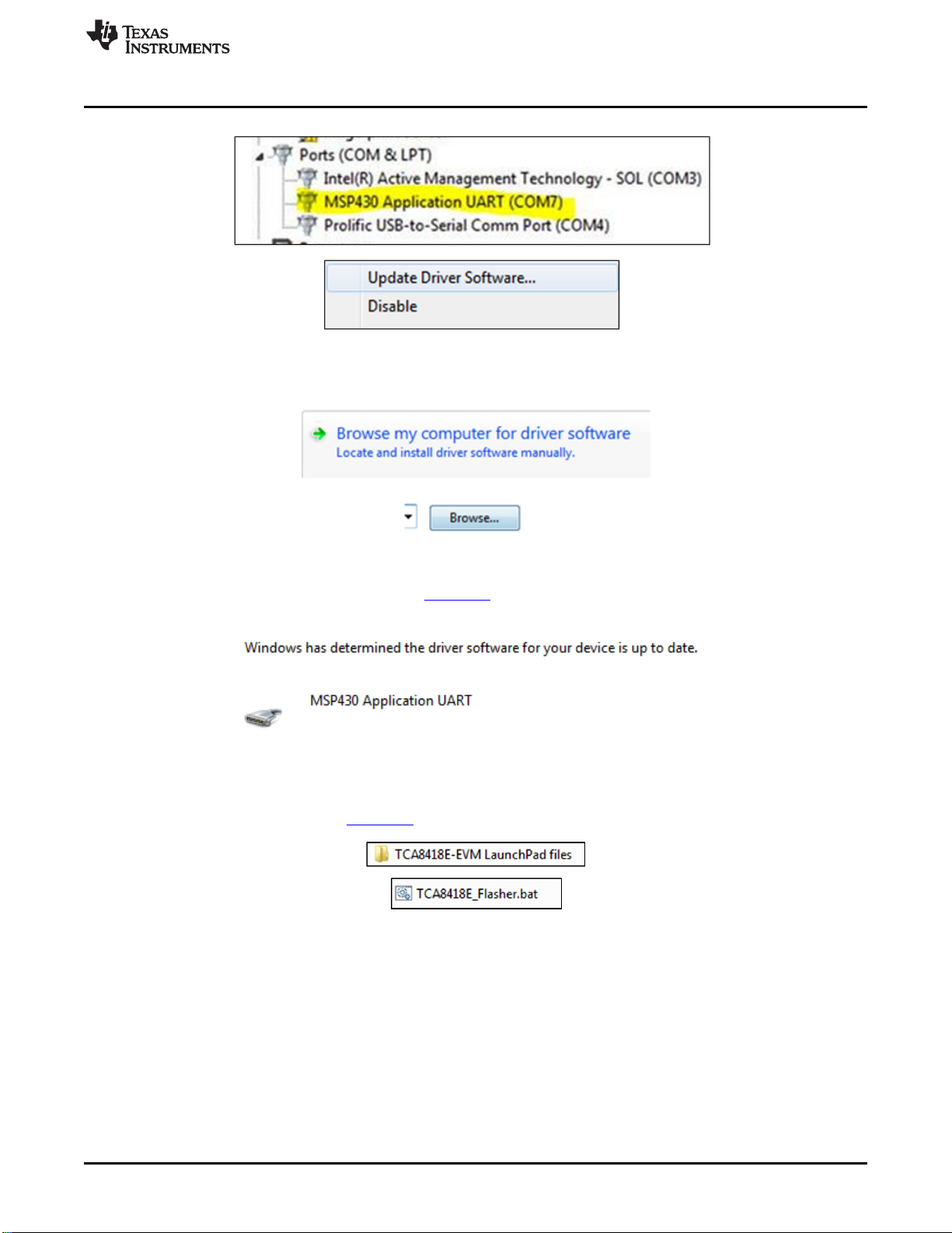
6 Updating Driver Software in Device Manager............................................................................ 7
7 Browsing for the Driver Software .......................................................................................... 7
8 Successful Installation of the MSP430 LaunchPad Drivers............................................................ 7
9 Flashing the MSP430 ....................................................................................................... 7
10 Successfully Flashed MSP430............................................................................................. 8
11 Installing the TCA8418E-EVM GUI........................................................................................ 9
12 TCA8418E-EVM GUI After Connecting the LaunchPad to the Computer ........................................... 9
13 TCA8418E-EVM GUI After Connecting the LaunchPad to the Computer.......................................... 11
14 Key Press Matrix Display While Holding Down the Middle Button (SW12)......................................... 12
15 Main Configuration and Input Register Display ........................................................................ 12
16 Reading Register 0x0E.................................................................................................... 13
17 Result of Reading Register 0x0E ........................................................................................ 13
18 Writing 0xA6 to Register 0x0E............................................................................................ 13
19 Result of Writing 0xA6 to Register 0x0E................................................................................ 13
20 TCA8418E-EVM Schematic .............................................................................................. 14
21 PCB Layer 1 (Top Layer).................................................................................................. 15
22 PCB Layer 2 (GND)........................................................................................................ 16
23 PCB Layer 3 (VCC)........................................................................................................ 17
1
SLVUAA2–August 2014 TCA8418E Keypad Scan EVM
Submit Documentation Feedback Copyright © 2014, Texas Instruments Incorporated

Information About Cautions and Warnings
www.ti.com
24 PCB Layer 4 (Bottom Layer).............................................................................................. 18
List of Tables
1 Device and Package Configurations ...................................................................................... 3
2 Default TCA8418E Register Values When Using the LaunchPad................................................... 10
3 Bill of Materials ............................................................................................................. 19
1 Information About Cautions and Warnings
CAUTION
This EVM contains components that can potentially be damaged by
electrostatic discharge. Always transport and store the EVM in its supplied ESD
bag when not in use. Handle using an antistatic wristband. Operate on an
antistatic work surface. For more information on proper handling, see the
Electrostatic Discharge (ESD) application note (SSYA008).
The information in a caution or a warning is provided for your protection. Read each caution and warning
carefully.
2 Items Required for Operation
The following items are required to use the TCA8418E-EVM:
• TCA8418E-EVM
• TCA8418E datasheet (SCPS222)
• One power supply for VCC
– 3.3 V at 100 mA recommended
3 Items Recommended for Operation
The following items are recommended for use with the TCA8418E-EVM:
• MSP430 LaunchPad
– Recommended rev 1.5
– MSP430G2553 installed
• USB standard-A to mini-B cable
• Computer running Microsoft®Windows®7 with 1 available USB port
4 Introduction
This document is the user’s guide for the TCA8418E-EVM. The TCA8418E-EVM can be used as a
standalone system or paired with the MSP-EXP430G2 LaunchPad to facilitate power and I2C
communication. When paired with the LaunchPad, The TCA8418E-EVM GUI can be used to read from or
write to internal registers of the TCA8418E keypad scan IC, allowing the user to control the states of the
I/O pins as well as see key presses in real-time.
Microsoft, Windows are registered trademarks of Microsoft Corporation.
2TCA8418E Keypad Scan EVM SLVUAA2–August 2014
Submit Documentation Feedback
Copyright © 2014, Texas Instruments Incorporated

COL9 COL8 COL7 COL6 COL5 COL4
GND VCC ROW7 ROW6 ROW5 ROW4
COL3 COL2 COL1
ROW3 ROW2 ROW1
COL0
ROW0
J5
Setup
www.ti.com
5 Setup
This section describes the header/jumper connections on the TCA8418E-EVM, installation of the firmware
on the MSP430 LaunchPad, installation of the software (GUI) on the computer, and getting started using
the TCA8418E-EVM with any of the supported devices.
5.1 Header/Jumper Connections Description
5.1.1 TP1: Power Input
Test point TP1 allows power input without the LaunchPad. The range is 1.65 V to 3.6 V.
5.1.2 TP2 and TP3: Ground
Test points TP2 and TP3 are connected to ground.
5.1.3 J1 and J2: MSP430 LaunchPad Interface Headers
Headers J1 and J2 are the connectors for the MSP430 LaunchPad to the TCA8418E-EVM.
5.1.4 J3: I2C Test Points
Header J3 is a test point for SDA and SCL, and allows I2C input when the LaunchPad is not present.
5.1.5 J4: RESET and Interrupt Test Points
Test point J4 is a test point for the RESET input, INT output, and CAD_INT output.
5.1.6 J5: Keypad Extension Header
Header J5 allows extension of the functionality of the TCA8418E-EVM onto a larger keypad or GPIO
expander board.
Figure 2. Header J5 Connections to TCA8418E Pins (Top View)
5.1.7 SW1, SW2, SW3, SW11, SW12, SW13, SW21, SW22, SW23: Keypad Switches
These switches are named in accordance with the Key Value Assignment table in the TCA8418E
(SCPS222) datasheet. They are for ROW0-ROW2 and COL0-COL2, which are programmed as keypad
I/Os, by default, on the TCA8418E-EVM.
4TCA8418E Keypad Scan EVM SLVUAA2–August 2014
Submit Documentation Feedback
Copyright © 2014, Texas Instruments Incorporated

www.ti.com
Setup
5.2 LaunchPad Hardware/Firmware Setup
If using the TCA8418E-EVM GUI, the MSP430 LaunchPad board needs to be configured properly in order
to flash the processor with the TCA8418E-EVM firmware. Implement the following steps before using the
TCA8418E-EVM in conjunction with the LaunchPad:
1. With the LaunchPad unplugged, configure the headers on the LaunchPad to be in HW UART mode by
attaching jumpers on the headers indicated by the yellow boxes in Figure 3.
Figure 3. Proper Jumper Configuration on the LaunchPad
5
SLVUAA2–August 2014 TCA8418E Keypad Scan EVM
Submit Documentation Feedback Copyright © 2014, Texas Instruments Incorporated

Setup
www.ti.com
2. Place the TCA8418E-EVM on top of the LaunchPad so that all connectors on J1 and J2 of the
LaunchPad are inserted into J1 and J2 of the TCA8418E-EVM and J7 on the TCA8418E-EVM is on
the same side as the mini-USB connector of the LaunchPad.
Figure 4. Proper Orientation for the TCA8418E-EVM on the LaunchPad.
3. Download the firmware (for the MSP430) and software (graphical user interface, or GUI) in a zipped
folder (SLVC601) located on the TCA8418E-EVM webpage on ti.com.
4. Right-click on the zip folder and select Extract All.
5. Click Extract.
6. Plug in the MSP430 LaunchPad to the computer.
7. Open Device Manager (Type “devmgmt.msc” into the Start menu and hit Enter):
Figure 5. Opening Device Manager in Windows
8. Select the MSP430 Application (see Figure 6), right click →Properties, and click Update Driver
Software. The MSP430 Application may appear either in Ports or Other Devices.
6TCA8418E Keypad Scan EVM SLVUAA2–August 2014
Submit Documentation Feedback
Copyright © 2014, Texas Instruments Incorporated

www.ti.com
Setup
Figure 6. Updating Driver Software in Device Manager
9. Select Browse my computer.
Figure 7. Browsing for the Driver Software
10. Select the folder where you extracted [SLVC601].zip.
11. Click Next. Click Close after you see the following:
Figure 8. Successful Installation of the MSP430 LaunchPad Drivers
12. Flash the MSP430 by double-clicking TCA8418E_Flasher.bat in the TCA8418E-EVM LaunchPad Files
folder where you extracted [SLVC601].zip.
Figure 9. Flashing the MSP430
7
SLVUAA2–August 2014 TCA8418E Keypad Scan EVM
Submit Documentation Feedback Copyright © 2014, Texas Instruments Incorporated

Setup
www.ti.com
13. Verify that the command window says “no errors” and then press any key to close the window. A
successful flash of the firmware results in the following command line prompt:
Figure 10. Successfully Flashed MSP430
14. Press any key to continue.
8TCA8418E Keypad Scan EVM SLVUAA2–August 2014
Submit Documentation Feedback
Copyright © 2014, Texas Instruments Incorporated

www.ti.com
Setup
5.3 GUI Software Setup
1. Run setup.exe, located in the TCA8418E_GUI folder. From now on, the TCA8418E software is
available under the Start menu in Programs →Texas Instruments, Inc →TCA8418E.exe.
Figure 11. Installing the TCA8418E-EVM GUI
2. If the GUI does not launch automatically, run the installed TCA8418E-EVM GUI program from the Start
menu.
3. The GUI looks like the following image when it is opened and the LaunchPad is connected:
Figure 12. TCA8418E-EVM GUI After Connecting the LaunchPad to the Computer
9
SLVUAA2–August 2014 TCA8418E Keypad Scan EVM
Submit Documentation Feedback Copyright © 2014, Texas Instruments Incorporated

Setup
www.ti.com
5.4 Default Register Settings in the TCA8418E when Using the LaunchPad
Upon startup, the MSP430 LaunchPad configures the TCA8418E to work as a keypad scanner with the
following values:
Table 2. Default TCA8418E Register Values When Using the LaunchPad
Register Register Name Default Value for EVM Comment
0x00 Reserved 0x97 Interrupts enabled (except Overflow)
0x01 CFG 0x00
0x02 INT_STAT 0x00
0x03 KEY_LCK_EC 0x00
0x04 KEY_EVENT_A 0x00
0x05 KEY_EVENT_B 0x00
0x06 KEY_EVENT_C 0x00
0x07 KEY_EVENT_D 0x00
0x08 KEY_EVENT_E 0x00
0x09 KEY_EVENT_F 0x00
0x0A KEY_EVENT_G 0x00
0x0B KEY_EVENT_H 0x00
0x0C KEY_EVENT_I 0x00
0x0D KEY_EVENT_J 0x00
0x0E KP_LCK_TIMER 0xA7
0x0F Unlock1 0x0C Key #12
0x10 Unlock2 0x0C Key #12 – Press twice to unlock
0x11 GPIO_INT_STAT1 0x00
0x12 GPIO_INT_STAT2 0x00
0x13 GPIO_INT_STAT3 0x00
0x14 GPIO_DAT_STAT1 0xFF
0x15 GPIO_DAT_STAT2 0xFF
0x16 GPIO_DAT_STAT3 0x03
0x17 GPIO_DAT_OUT1 0x00
0x18 GPIO_DAT_OUT2 0x00
0x19 GPIO_DAT_OUT3 0x00
0x1A GPIO_INT_EN1 0x00
0x1B GPIO_INT_EN2 0x00
0x1C GPIO_INT_EN3 0x00
0x1D KP_GPIO1 0xFF ROW0 through ROW7: keypad scan
0x1E KP_GPIO2 0xFF COL0 through COL7: keypad scan
0x1F KP_GPIO3 0x00
0x20 GPI_EM1 0x00
0x21 GPI_EM2 0x00
0x22 GPI_EM3 0x00
0x23 GPIO_DIR1 0x00
0x24 GPIO_DIR2 0x00
0x25 GPIO_DIR3 0x00
0x26 GPIO_INT_LVL_1 0x00
0x27 GPIO_INT_LVL_2 0x00
0x28 GPIO_INT_LVL_3 0x00
0x29 DEBOUNCE_DIS_1 0x00
0x2A DEBOUNCE_DIS_2 0x00
0x2B DEBOUNCE_DIS_3 0x00
10 TCA8418E Keypad Scan EVM SLVUAA2–August 2014
Submit Documentation Feedback
Copyright © 2014, Texas Instruments Incorporated
Ce manuel convient aux modèles suivants
1
Table des matières


