ANTENNA
CONNECTOR
SIM
CARD
J10
TO
RJ-31x
TO
ALARM
PANEL
AC
INPUT STC
OUTPUTS
RADIO
4AH
OR 7AH
BATTERY
RED &
BLACK
TO
BATTERY
LED MODE
SELECTOR
OUT=NORMAL
IN=RSSI
1 2 3 4 5
STATUS LEDS
SIGNAL STRENGTH
AC
LED 6
J6
J5
12V AC
800ma
T
R
EARTH
GROUND
JP5
RJ-31x
STC CONTACTS
RATED @100ma
STC 1 (N.O.)
STC 2 (N.C.)
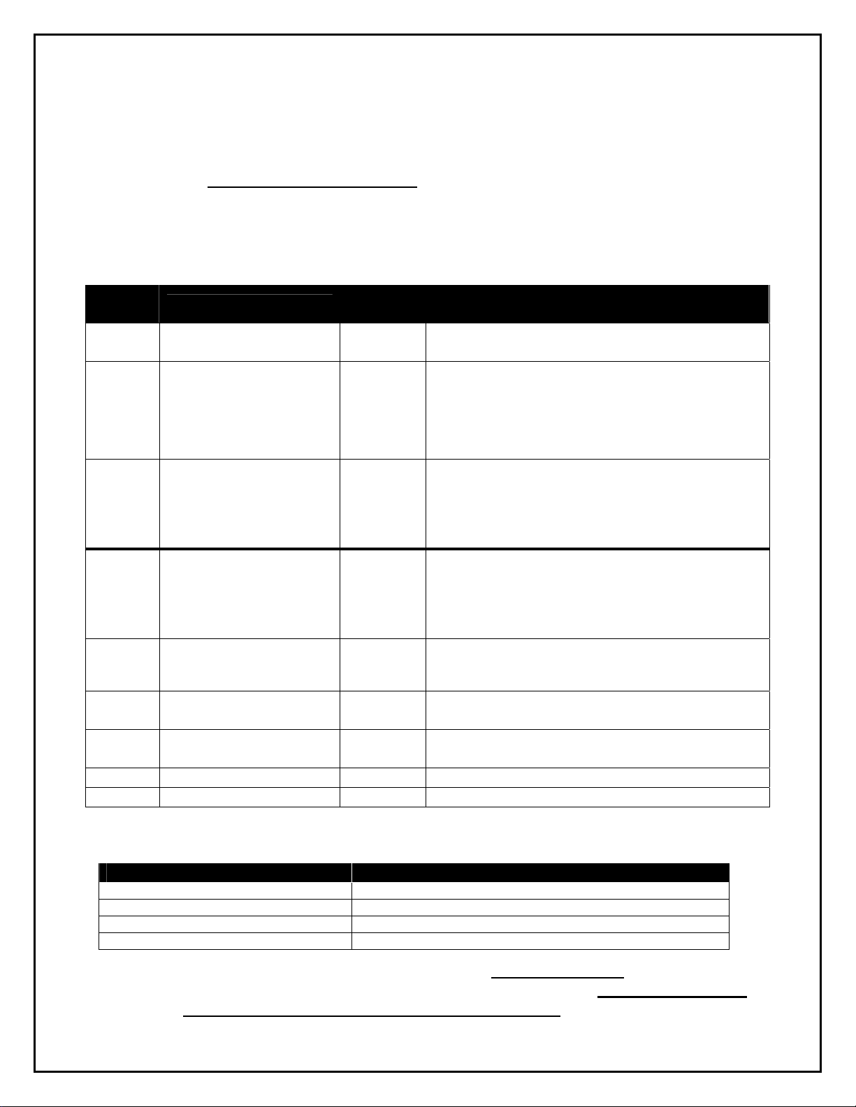
SYSTEM STATUS LEDS
NORMAL MODE
LED #1 GREEN
ON = RADIO INITIALIZING
FLASH = COMMUNICATING
LED #2 RED
ON = WAITING FOR RESPONSE
If flashing with LED #5 = DENIED (NACK)
LED #3 YELLOW
ON = MODE 1 (TELCO Primary)
OFF = MODE 2 (CELL Primary)
FLASH = C/C OFF HOOK CELL
LED #4 RED
SYSTEM TROUBLE, STC (See Table)
LED #5 GREEN
REGISTRATION (See Table)
SYSTEM TROUBLE,
STC (LED #4)
1 FLASH = AC LOW/MISSING
2 FLASH = LBC LOW BATTERY
3 FLASH = LFC LINE FAULT
4 FLASH = NSC NO SERVICE
5 FLASH = RFC RADIO FAILURE
6 FLASH = DTF DIAL TONE FAIL
24 HOUR
ZONE
24 HOUR
ZONE
TELCO
DIALER
HOST
ALARM
PANEL
WIRELESS VOICE LINE
TG-8 ONLY
REGISTRATION
(LED #5)
ON = UNIT REGISTERED
OFF = UNIT NOT REGISTERED
If flashing with LED #2 = DENIED (NACK),
Call Technical Support.
If all LED's flashing = NO RESPONSE,
Check Signal Strength.
SYSTEM STATUS LEDS
RSSI MODE
RSSI Value LED's Lighted RF dBm
NO SVC LED 1* = on, 2-4 = off < -111 dBm
1 ½ LED 1 = on, 2 = flash, 3-4 = off > -110 dBm
2 LED 1-2 = on, 3-4 = off > -100 dBm
2 ½ LED 1-2 = on, 3 = flash, 4 = off > -90 dBm
(Minimum Signal Recommended)
3 LED 1-3 = on, 4 = off > -80 dBm
3 ½ LED 1-3 = on , 4 = flash > -70 dBm
4 LED 1-4 = on > -60 dBm
*Note: LED #5 ON INDICATES MORE THAN ONE TOWER
CAUTION:
INCORRECT CONNECTIONS MAY
RESULT IN DAMAGE TO THE UNIT
www.Telguard.com
REFER TO INSTALLATION AND OPERATING INSTRUCTIONS MANUAL.
THIS DEVICE COMPLIES WITH FCC RULES PART 68 AND 15.
TELULAR CORPORATION
420 Thornton Road, Suite 109
Lithia Springs, GA 30122
(800) 229-2326
Fax: 678-945-1651
Telguard Digital models TG-7 & TG-8
QUICK INSTALLATION GUIDE
Installation Summary
There are six steps in installing Telguard properly. IF YOU DO NOT
PROCEED IN THE ORDER AND MANNER PRESCRIBED, YOU MAY
NOT COMPLETE THE INSTALLATION IN THE TIME ALLOCATED.
STEP 1: REGISTER FOR CELLULAR SERVICE
Complete the Activation Form online at www.Telguard.com or fax
the form to Telular Cellular Service prior to leaving for the job site.
Telular requires this information to register and activate the unit.
STEP 2: LOCATE UNIT AND MEASURE SIGNAL STRENGTH (RSSI)
First, you will be confirming that Telguard has adequate cellular signal
strength. Put J10 across both pins, LEDS will now indicate signal strength,
minimum recommended is 2 ½ (2 on solid and the third flashing).
STEP 3: TRANSMIT C/C ALARMS OVER THE TELCO CONNECTION
Connect C/C and telco line to the Telguard. Trip a simple alarm on the C/C
and transmit over the telco line. This step is important to verify that the C/C
is programmed with valid account code and central station information
before transmitting signals through the cellular network.
STEP 4: PROGRAM,ACTIVATE &TRANSMIT C/C ALARMS OVER
THE CELLULAR RADIO NETWORK
Next, you will be programming the Telguard unless the default settings are
what you want. Then connect the C/C's digital dialer output to Telguard and
verify that alarm signals can be reliably sent over cellular to the central
station digital receiver. The incoming telco line is not connected to Telguard
during this step. A minimum of two alarm signals must be transmitted.
(NOTE: THE FIRST ALARM WILL CONFIRM REGISTRATION AND
ACTIVATE THE UNIT WITH THE TELULAR COMMUNICATION CENTER.
IT WILL NOT BE TRANSMITTED TO THE CENTRAL STATION.ALL
SIGNALS AFTER THE FIRST ARE SENT TO THE CENTRAL STATION.)
STEP 5: CONNECT SUPERVISORY TRIP OUTPUTS
Next, you will wire Telguard's supervisory trip outputs to the C/C and then test.
STEP 6: COMPLETE THE INSTALLATION
Your last step will be to check the jumper setting of J10 (LED mode, open =
normal), attach earth ground, and permanently mount the unit. 56031003