TeeJet Technologies Dynajet FLEX 7140 Manuel utilisateur
DYNAJET® FLEX 7140
INSTALLATION, SETUP AND USER GUIDE
Software version 1.03
with optional dual nozzle mode

Copyrights
© 2017 TeeJet Technologies. All rights reserved. No part of this document or the computer programmes described in it may be reproduced,
copied, photocopied, translated, or reduced in any form or by any means, electronic or machine readable, recording or otherwise, without
prior written consent from TeeJet Technologies.
Trademarks
Unless otherwise noted, all other brand or product names are trademarks or registered trademarks of their respective companies or
organisations.
Limitation of Liability
TEEJET TECHNOLOGIES PROVIDES THIS MATERIAL “AS IS” WITHOUT WARRANTY OF ANY KIND, EITHER EXPRESSED OR
IMPLIED. NO COPYRIGHT LIABILITY OR PATENT IS ASSUMED. IN NO EVENT SHALL TEEJET TECHNOLOGIES BE LIABLE FOR ANY
LOSS OF BUSINESS, LOSS OF PROFIT, LOSS OF USE OR DATA, INTERRUPTION OF BUSINESS, OR FOR INDIRECT, SPECIAL,
INCIDENTAL, OR CONSEQUENTIAL DAMAGES OF ANY KIND, EVEN IF TEEJET TECHNOLOGIES HAS BEEN ADVISED OF SUCH
DAMAGES ARISING FROM TEEJET TECHNOLOGIES SOFTWARE.
Safety Information
TeeJet Technologies is not responsible for damage or physical harm caused by failure to adhere to the following safety
requirements.
As the operator of the vehicle, you are responsible for its safe operation.
The DynaJet Flex is not designed to replace the vehicle’s operator.
Be sure that the area around the vehicle is clear of people and obstacles before and during engagement.
The DynaJet Flex is designed to support and improve efciency while working in the eld. The driver has full responsibility for the quality and
work related results.

iii
98-05345-EN R1
DynaJet®Flex 7140
Table of contents
DYNAJET® FLEX OVERVIEW 1
INSTALLATION 1
CONSOLE 1
INSTALLATION 2
DynaJetFlex® drivers ....................................................................................................................................................................................2
Power ..................................................................................................................................................................................................................2
Nozzle harnesses ............................................................................................................................................................................................2
CAN cables & terminators............................................................................................................................................................................2
DynaJetFlex® interface.................................................................................................................................................................................2
Boom interface module (BIM) (optional) ...............................................................................................................................................2
Pressure sensor interface (optional) ........................................................................................................................................................2
INITIAL STARTUP 5
Favorites.............................................................................................................................................................................................................5
Setup...................................................................................................................................................................................................................5
Units.........................................................................................................................................................................................6
Number of sections..................................................................................................................................................................6
Number of nozzles...................................................................................................................................................................6
Maximum pressure sensor value.............................................................................................................................................6
Nozzle selection ..............................................................................................................................................................................................7
Select nozzle series.........................................................................................................................................................7
Select nozzle capacity .....................................................................................................................................................7
Ready to pressure test the system............................................................................................................................................................7
OPERATIONS 8
Work screen ......................................................................................................................................................................................................8
On screen indicators................................................................................................................................................................8
Droplet size chart.............................................................................................................................................................8
Diagnostics .................................................................................................................................................................................................... 10
Error warnings............................................................................................................................................................................................... 11
USER SETTINGS 13
DYNAJETFLEX® NOZZLE SELECTION 15
Nozzle selection example......................................................................................................................................................................... 16
TUNING DYNAJETFLEX® 17
Tuning the control console valve........................................................................................................................................................... 17
Tuning the DynaJetFlex system ............................................................................................................................................................ 17
55295 E-CHEMSAVER® MAINTENANCE INSTRUCTIONS 18
General disassembly and reassembly.................................................................................................................................................. 18
APPLICATION RATES AT GIVEN SPEED AND NOZZLE CAPACITY 19
SPEED RANGE AVAILABLE AT GIVEN NOZZLE SIZE AND APPLICATION RATE 20

1www.teejet.com
DynaJet®Flex 7140
DYNAJET® FLEX OVERVIEW
The DynaJet Flex controller works in conjunction with an existing rate controller that regulates ow via a control valve or pump regulation to
achieve a target application rate while maintaining target droplet size(s) when a speed change occurs. This system only works with automatic
rate controllers that use ow based monitoring systems and not pressure based monitoring systems. Automatic rate controllers equipped for
both ow and pressure based control should have the pressure-based system disabled to work in conjunction with DynaJet Flex.
The independent automatic rate controller loop performs the same as it would if the DynaJet Flex controller were not present. The
DynaJet Flex controller changes ow output to each individual nozzle based upon input provided from the operator about the optimum droplet
size (pressure) for the application.
INSTALLATION
CONSOLE
The DynaJet Flex console is designed to provide years of service under typical agricultural and turf operating conditions. A tight tting
enclosure means that typical dusty environments will not cause operational problems. While occasional splashing of water will not damage
the unit, the DynaJet Flex console is not designed for direct exposure to rain. Take care not to operate the DynaJet Flex console in wet
conditions.
Figure 1: DynaJet Flex 7140 console front and back
to DynaJet interface
harness connection
Power switch
USB port
Standard RAM bracket
Bright touch screen

2
98-05345-EN R1
DynaJet®Flex 7140
CAN Start Terminator
(female)
at Boom Section 1
DynaJet Solenoids
to CAN connection
DynaJet Solenoids
Power Distribution Module
Tip Harness
DynaJet Driver
DynaJet Solenoids DynaJet Solenoids
Tip Harness
DynaJet Driver
DynaJet Solenoids DynaJet Solenoids
Tip Harness
DynaJet Driver
DynaJet Solenoids DynaJet Solenoids
Tip Harness
DynaJet Driver
INSTALLATION
DynaJetFlex® drivers
There will be one DynaJet Flex driver 78-05124 per eight (8) nozzles.
• Mount each DynaJet Flex driver centered within the eight (8)
nozzles it controls.
Power
Power will be sourced from the battery using the 60 amp fused cable
45-05943.
Power from the battery will be routed to the boom using the 6 gauge
power cables 45-05942-xx
The Power distribution modules 78-05121-xx will connect to the
45-05942-xx cables.
Power will then route from 78-05121-xx to each DynaJet Flex
driver 78-05122 using cables 45-05971-xx, and 45-05997-xx or
45-05998-xx.
Nozzle harnesses
When installing Nozzle harnesses 45-04005-xx-xx always start with
section 1 and continue to the last section.
Nozzle harnesses are designed for your specic nozzle spacing.
Always start with nozzle #1 and work left to right (while facing in
the machine’s forward direction.
CAN cables & terminators
The Start terminator 45-04006-START must be connected to the
DynaJet Flex driver 78-05124 for section 1.
CAN cables must be connected in series.
The End terminator 45-04006-END must be connected to the Driver
module 78-05124 for the last section.
DynaJetFlex® interface
The DynaJet Flex interface 78-05123 connects to the DynaJet Flex
interface harness 45-10193:
The DynaJet Flex interface harness connects to
a. The Console 75-30119 (extension cable may be used)
b. Power 12V for powering the CAN
c. CAN
d. Pressure sensor
e. Boom sense
The DynaJet Flex interface can be mounted in the cab or outside
depending upon your installation.
Boom interface module (BIM) (optional)
The Boom interface module (BIM) 78-05091 is used by the
DynaJet Flex system for boom sense.
The BIM harness connects between the BIM and the CAN.
On the BIM harness 45-10195, the Boom sense wires (or ying
leads) are supplied to tie into existing machine boom section 12V
ON/0V OFF outputs.
If not using 45-10195, some machine specic harnesses are
available.
The BIM can be mounted in the cab or outside depending upon your
installation.
Pressure sensor interface (optional)
Pressure sensor interface 78-05133 can be used if the DynaJet Flex
interface is mounted in the cab and there is a substantial distance to
the boom.
• The Pressure sensor interface should be mounted close to the
boom manifold
Figure 2: Installation diagram

3www.teejet.com
DynaJet®Flex 7140
Figure 3: System diagram
(A) DynaJet 7140 console w/RAM mount kit
90-02887
Kit includes: console and mount
(K) Sensor cable
45-05887: 3' / 1 m
45-05886: 25' / 7.6 m
(G) Pressure sensor
16-05015
(H) Boom harness
45-10178 to IC18
45-10179 to Raven 440
45-10181 to Raven Envizio
45-10186 to 15 Section boom harness
(J) CAN Terminator
45-04006-END
(L) Driver harness
45-04005-06-20: 6 nozzle, 20” / 50 cm spacing
45-04005-06-20-END: 6 nozzle, 20" / 50 cm spacing w/termination
45-04005-06-20-START: 6 nozzle, 20" / 50 cm spacing w/termination
45-04005-08-20: 8 nozzle, 20” / 50 cm spacing
45-04005-08-20-END: 8 nozzle, 20" / 50 cm spacing w/termination
45-04005-08-20-START: 8 nozzle, 20" / 50 cm spacing w/termination
(M) Nozzle extension
45-04001-40: 40" / 1 m
45-04001-80: 80" / 1 m
(I) CAN terminator
45-04006-START
(F) DynaJet Flex driver
78-05124 (E) CAN extension cable
45-04006-03: 3’ / 1 m
45-04006-07: 7’ / 2 m
45-04006-13: 13’ / 4 m
45-04006-20: 20’ / 6 m
to battery power to battery power to battery power
(C) DynaJet Flex interface harness
45-10193
(D) DynaJet Flex interface
78-05123
(B) Console extension cable
45-05900: 5' / 1.5 m
45-05901: 10' / 3 m
45-05902: 20' / 6 m
45-05903: 40' / 12 m
tobattery power

4
98-05345-EN R1
DynaJet®Flex 7140
Item Part # Description Illustration
A90-02887 DynaJet Flex 7140 console
B45-05900: 5' / 1.5 m
45-05901: 10' / 3 m
45-05902: 20' / 6 m
45-05903: 40' / 12 m
Console extension cable
C45-10193 DynaJet Flex interface
harness
D78-05123 DynaJet Flex interface
E45-04006-03: 3' / 1 m
45-04006-07: 7' / 2 m
45-04006-13: 13' / 4 m
45-04006-20: 20' / 6 m
CAN extension cable
F78-05124 DynaJet Flex driver
G16-05015 Pressure sensor
H45-10178 to IC18
45-10179 to Raven 440
45-10181 to Raven Envizio
45-10186 to 15 Section Boom Harness
Boom harness
I45-05855 CAN terminator-START
J45-05856 CAN terminator-END
K45-05887: 3' / 1 m
45-05886: 25' / 7.6 m
Pressure sensor cable
L45-04005-06-20: 6 nozzle, 20” / 50 cm spacing
45-04005-06-20-END: 6 nozzle, 20" / 50 cm spacing w/termination
45-04005-06-20-START: 6 nozzle, 20" / 50 cm spacing w/termination
45-04005-08-20: 8 nozzle, 20” / 50 cm spacing
45-04005-08-20-END: 8 nozzle, 20" / 50 cm spacing w/termination
45-04005-08-20-START: 8 nozzle, 20" / 50 cm spacing w/termination
Driver harness
M45-04001-40: 40" / 1 m
45-04001-80: 80" / 2 m
Nozzle extension
5www.teejet.com
DynaJet®Flex 7140
INITIAL STARTUP
This section will explain basic setup of the values required for
rst-time setup of a DynaJet Flex system. When these settings are
completed, initial operation and ne-tuning should be possible.
To access setup menu from the work screen, touch centre of the
screen.
1. Select from:
►Favorites – The FAVORITE icon represents favorite spray
nozzles. This function automatically stores the most recent
ve (5) nozzles chosen. Use this to quickly access your most
frequently used spray nozzles.
►Setup – The SETUP icon is used to access settings. This
will enter the conguration menu.
►Nozzle selection – The SPRAY NOZZLE icon is used to
select the spray nozzle style and capacity. Once chosen here,
the spray nozzle style and capacity is automatically added to
the favorites list.
►Diagnostics – The DIAGNOSTICS icon is used to
diagnose and operating issues of the system and booms. The
diagnostics menu is described in the operations chapter.
2. Press HOME icon to return to the main work screen.
Figure 4: Options menu
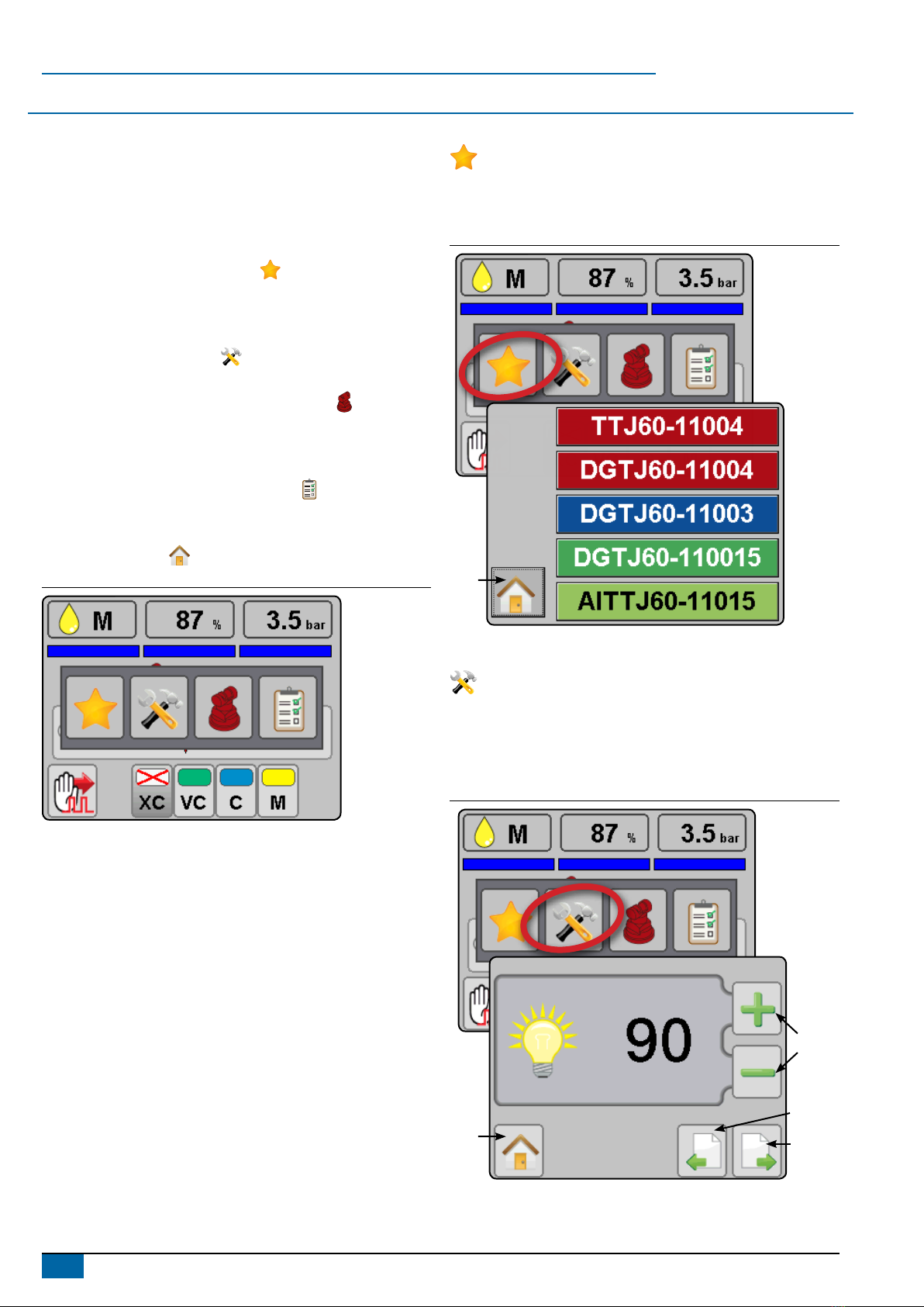
Favorites
The favorite icon represents favorite spray nozzles. This
function automatically stores the most recent ve (5) nozzles
chosen. Use this to quickly access your most frequently used
spray nozzles.
Figure 5: Favorites
Work
screen
Setup
The setup icon is used to access settings. This will enter the
conguration menu. Selections are automatically saved when
adjusted.
NOTE: Not all settings are listed below. See “User settings” section
of this guide for additional settings and details.
Figure 6: Setup
Previous page
Next page
Change value
Work
Screen

6
98-05345-EN R1
DynaJet®Flex 7140
Units
Sets the units to US (psi) or Metric (bar).
Figure 7: Units
Number of sections
Set the number of boom sections. This should match the number of
sections used on the spray controller. Range is 1 to 15.
Figure 8: Number of sections
Number of nozzles
Set the number of nozzles for each section. This value should
match the number of nozzles used on the spray controller. When
programming is complete, values should match and show in green.
Range is 1 to 120.
►Green matching values indicate a match between the number
of nozzles detected and the number of nozzles programmed.
►Red mismatching values indicate a mismatch between the
number of nozzles detected and the number of nozzles
programmed.
NOTE: Mismatched values will stop screen advancement until
number of nozzles detected and number of nozzles
programmed match
Figure 9: Number of nozzles – Match
Figure 10: Number of nozzles – Mismatch
Maximum pressure sensor value
Verify this value by looking at the pressure sensor description.
Values will be either 10 bar or 25 bar.
If pressure value displayed on the DynaJet Flex console are not
accurate compared to a mechanical gauge, adjust this value until
there is a match.
►Increasing the value will reduce the pressure value displayed
during operation
►Decreasing this value will increase the pressure value
displayed during operation
Figure 11: Max. pressure sensor value

7www.teejet.com
DynaJet®Flex 7140
Nozzle selection
Accesses the nozzle selection process to select which nozzle
is to be used. At this time only TeeJet nozzles are supported.
Figure 12: Nozzle selection
Select nozzle series
Use the green up and down arrows to highlight the correct spray
nozzle series/family.
Figure 13: Select nozzle series
Select nozzle capacity
With the correct nozzle capacity highlighted, select the HOME icon
to return to operating mode. The selected nozzle will be active
and will automatically be added to the favorites list.
Figure 14: Select nozzle capacity
Ready to pressure test the system
1. Ensure that current rate control system is operating at the optimum level. Set DynaJet Flex operating mode to manual and set PWM duty
cycle at 100%. This will make the system operate as if DynaJet Flex was not present. Use this conguration to verify the rate control
system is operating normally.
2. Keep DynaJet Flex operating mode on manual and change PWM duty cycle to 50%. Use this conguration to verify the rate control
system is operating normally.
3. Conrm boom section functionality by observing the row of rectangles below the on the operating display. Switch the master switch ON
(on rate control or other boom section control switches) and individual sections one at a time. Make sure each section appropriately
changes colour to blue. With the master switch OFF, all active sections will be grey again.
4. Start pump and ensure no leaks.
5. Verify pressure on mechanical gauge matches the digital pressure display within reason. If not, adjust max. pressure sensor value as
previously described.
6. Congure in PWM mode DynaJet Flex at duty cycle of 50%. Conrm each e-ChemSaver (ECS) is pulsating.
At this point the system is functioning. Further details for ne-tuning the system are available in the user settings section of this guide.
Table des matières
Autres manuels TeeJet Technologies Système de contrôle


