Technosoft iPOS360x MX Manuel d'utilisation et d'entretien

© Technosoft 2023 - 1 - IO-iPOS360x Technical Reference
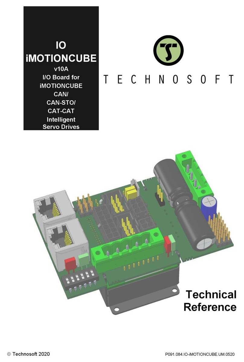
IO
iPOS360x
v.11A
I/O Board for
iPOS360x CAN/CAT
Intelligent
Servo Drives
Technical
Reference
©Technosoft 2023 P091.084.IO-iPOS360x.UM.0623

© Technosoft 2023 - 2 - IO-iPOS360x Technical Reference
1. Read This First
Whilst Technosoft believes that the information and guidance given in this manual is correct, all
parties must rely upon their own skill and judgment when making use of it. Technosoft does not
assume any liability to anyone for any loss or damage caused by any error or omission in the work,
whether such error or omission is the result of negligence or any other cause. Any and all such liability
is disclaimed.
All rights reserved. No part or parts of this document may be reproduced or transmitted in any form or
by any means, electrical or mechanical including photocopying, recording or by any information-
retrieval system without permission in writing from Technosoft S.A.
The information in this document is subject to change without notice.
About This Manual
This book is a technical reference manual for the iPOS360x VX-CAN/CAT extension boards version
11A that are included in the iPOS360x intelligent servo drives Starter Kits.
The IO iPOS360x extension board can be one of the following products:
iPOS360x VX-CAN IO
p/n P028.002.E880
For drives with CAN.
iPOS360x VX-CAT IO
p/n P028.002.E890
For drives with EtherCAT.
Paragraph 3.3 shows how to quickly identify the IO-iPOS360x version. If your IO-iPOS360x is
an older version, you can find the appropriate manual on the Technosoft web page.
Notational Conventions
This document uses the following conventions:
iPOS360x –any iPOS3602 or iPOS3604 drive that can be connected to this I/O extension
iPOS360x VX-CAN –iPOS3602 VX-CAN and iPOS3604 VX-CAN drives with CAN
iPOS360x VX-CAT –iPOS3602 VX-CAT and iPOS3604 VX-CAT drives with EtherCAT.
Require presence of the EtherCAT interface card.
TML –Technosoft Motion Language
Related Documentation
iPOS360x VX Technical Reference (part no. P091.028.iPOS360x.VX.UM.xxxx) –
describes the hardware installation of the iPOS360x VX family of intelligent servo drives
including the technical data, the connectors and the wiring diagrams needed for
installation and an overview of the setup steps and motion programming options
iPOS360x MX Technical Reference (part no. P091.028.iPOS360x.MX.UM.xxxx) –
describes the hardware installation of the iPOS360x MX family of intelligent servo drives
including the technical data, the connectors and the wiring diagrams needed for
installation and an overview of the setup steps and motion programming options
Help of the EasySetUp software –describes how to use EasySetUp to quickly setup any
Technosoft drive for your application using only 2 dialogues. The output of EasySetUp is
a set of setup data that can be downloaded into the drive EEPROM or saved on a PC
file. At power-on, the drive is initialized with the setup data read from its EEPROM. With
EasySetUp it is also possible to retrieve the complete setup information from a drive
previously programmed. EasySetUp includes a firmware programmer with allows you to
update your drive firmware to the latest revision. EasySetUp can be downloaded free
of charge from Technosoft web page
Motion Programming using EasyMotion Studio (part no. P091.034.ESM.UM.xxxx) –
describes how to use the EasyMotion Studio to create motion programs using in
Technosoft Motion Language (TML). EasyMotion Studio platform includes EasySetUp
for the drive/motor setup, and a Motion Wizard for the motion programming. The Motion
Wizard provides a simple, graphical way of creating motion programs and automatically

© Technosoft 2023 - 3 - IO-iPOS360x Technical Reference
generates all the TML instructions. With EasyMotion Studio you can fully benefit from a
key advantage of Technosoft drives –their capability to execute complex motions
without requiring an external motion controller, thanks to their built-in motion controller.
A demo version of EasyMotion Studio (with EasySetUp part fully functional) can
be downloaded free of charge from Technosoft web page
iPOS CANopen Programming (part no. P091.063.iPOS.UM.xxxx) –explains how to
program the iPOS drives using CANopen protocol and describes the associated object
dictionaries for the supported profiles
CANopen over EtherCAT Programming (part no. P091.064.UM.xxxx) –explains how to
program the Technosoft intelligent drives using CoE protocol and describes the
associated object dictionary.
TML_LIB v2.0 (part no. P091.040.v20.UM.xxxx) –explains how to program in C, C++,C#,
Visual Basic or Delphi Pascal a motion application for the Technosoft intelligent drives
using TML_LIB v2.0 motion control library for PCs. The TML_lib includes ready-to-run
examples that can be executed on Windows or Linux (x86 and x64).
TML_LIB_LabVIEW v2.0 (part no. P091.040.LABVIEW.v20.UM.xxxx) –explains how to
program in LabVIEW a motion application for the Technosoft intelligent drives using
TML_LIB_Labview v2.0 motion control library for PCs. The TML_Lib_LabVIEW includes
over 40 ready-to-run examples.
TML_LIB_S7 (part no. P091.040.S7.UM.xxxx) –explains how to program in a PLC Siemens
series S7-300 or S7-400 a motion application for the Technosoft intelligent drives using
TML_LIB_S7 motion control library. The TML_LIB_S7 library is IEC61131-3
compatible.
TML_LIB_CJ1 (part no. P091.040.CJ1.UM.xxxx) –explains how to program in a PLC
Omron series CJ1 a motion application for the Technosoft intelligent drives using
TML_LIB_CJ1 motion control library for PCs. The TML_LIB_CJ1 library is IEC61131-3
compatible.
TML_LIB_X20 (part no. P091.040.X20.UM.xxxx) –explains how to program in a B&R PLC
series X20 a motion application for the Technosoft intelligent drives using TML_LIB_X20
motion control library for PCs. The TML_LIB_X20 library is IEC61131-3 compatible
TechnoCAN (part no. P091.063.TechnoCAN.UM.xxxx) –presents TechnoCAN protocol –
an extension of the CANopen communication profile used for TML commands
If you Need Assistance …
If you want to …
Contact Technosoft at …
Visit Technosoft online
World Wide Web: http://www.technosoftmotion.com/
Receive general information
or assistance (see Note)
Ask questions about product
operation or report suspected
problems (see Note)
Make suggestions about,
or report errors in documentation.
World Wide Web: http://www.technosoftmotion.com/
Email: [email protected]
Tel: +41 (0)32 732 5500
Email: [email protected]
Mail: Technosoft SA
Avenue des Alpes 20
CH-2000 Neuchatel, NE
Switzerland

© Technosoft 2023 - 4 - IO-iPOS360x Technical Reference
Contents
1. Read This First .......................................................................................- 2 -
2. Safety information......................................................................................5
2.1. Warnings ..................................................................................................... 5
2.2. Cautions ...................................................................................................... 5
3. Product Overview.......................................................................................6
3.1. Introduction.................................................................................................. 6
3.2. Key Features ............................................................................................... 6
IO-iPOS360x Board Dimensions............................................................................. 7
3.3. IO-iPOS360x Board Version Identification .................................................. 8
4. Hardware Installation .................................................................................9
4.1. Mounting the iPOS360x VX board............................................................... 9
4.2. Mounting the iPOS360x MX board .............................................................. 9
4.3. Mounting the EtherCAT interface module ................................................. 10
4.4. Connectors ................................................................................................ 11
4.4.1. Connectors Layout........................................................................................... 11
4.4.2. J4 and J5 –CAN connectors ........................................................................... 11
4.4.3. J6 –Analog inputs connector........................................................................... 12
4.4.4. J7 –Digital I/O connector................................................................................. 12
4.4.5. J8 –Linear Hall, single-ended encoder and differential encoder connector...... 13
4.4.6. J9 –Motor supply and digital hall connector .................................................... 13
4.4.7. J11 –USB connector....................................................................................... 14
4.4.8. J12 –Power supply connector ......................................................................... 14
4.4.9. J13 and J14 –EtherCAT connectors ............................................................... 14
4.5. Jumper Settings ........................................................................................ 14
4.6. Axis ID Selection and CAN Protocol for iPOS360x VX-CAN drives .......... 16
4.7. Axis ID Selection for iPOX360x VX-CAT drives with EtherCAT protocol... 21
4.8. Installing and configuring the USB drivers................................................. 22
4.8.1. Installing the USB drivers................................................................................. 22
4.8.2. USB driver configuration .................................................................................. 23
4.9. First Power Up........................................................................................... 25
Appendix 1: IO-iPOS360x schematics............................................................. 26
Appendix 2: iPOS360x VX Plug-in Connector Pins ........................................27
J1 Connector pinout (A Side) ................................................................................ 27
J1 Connector pinout (B side)................................................................................. 28

© Technosoft 2023 5 IO-iPOS360x Technical Reference
2. Safety information
Read carefully the information presented in this chapter before carrying out the drive
installation and setup! It is imperative to implement the safety instructions listed hereunder.
This information is intended to protect you, the drive and the accompanying equipment during the
product operation. Incorrect handling of the drive can lead to personal injury or material damage.
Only qualified personnel may install, setup, operate and maintain the drive. A “qualified person” has
the knowledge and authorization to perform tasks such as transporting, assembling, installing,
commissioning and operating drives.
The following safety symbols are used in this manual:
WARNING!
SIGNALS A DANGER TO THE OPERATOR WHICH MIGHT CAUSE
BODILY INJURY. MAY INCLUDE INSTRUCTIONS TO PREVENT
THIS SITUATION
CAUTION!
SIGNALS A DANGER FOR THE DRIVE WHICH MIGHT DAMAGE
THE PRODUCT OR OTHER EQUIPMENT. MAY INCLUDE
INSTRUCTIONS TO AVOID THIS SITUATION
CAUTION!
INDICATES AREAS SENSITIVE TO ELECTROSTATIC
DISCHARGES (ESD) WHICH REQUIRE HANDLING IN AN ESD
PROTECTED ENVIRONMENT
2.1. Warnings
WARNING!
THE VOLTAGE USED IN THE DRIVE MIGHT CAUSE ELECTRICAL
SHOCKS. DO NOT TOUCH LIVE PARTS WHILE THE POWER
SUPPLIES ARE ON
WARNING!
TO AVOID ELECTRIC ARCING AND HAZARDS, NEVER CONNECT
/ DISCONNECT WIRES FROM THE DRIVE WHILE THE POWER
SUPPLIES ARE ON
WARNING!
THE DRIVE MAY HAVE HOT SURFACES DURING OPERATION.
WARNING!
DURING DRIVE OPERATION, THE CONTROLLED MOTOR WILL
MOVE. KEEP AWAY FROM ALL MOVING PARTS TO AVOID
INJURY
2.2. Cautions
CAUTION!
THE POWER SUPPLIES CONNECTED TO THE DRIVE MUST
COMPLY WITH THE PARAMETERS SPECIFIED IN THIS
DOCUMENT
CAUTION!
TROUBLESHOOTING AND SERVICING ARE PERMITTED ONLY
FOR PERSONNEL AUTHORISED BY TECHNOSOFT
CAUTION!
ALWAYS REMOVE THE JUMPERS: JP11, JP12, JP13, JP14, JP15,
JP16 WHEN THE ETHERCAT INTERFACE MODULE IS INSERTED

© Technosoft 2023 6 IO-iPOS360x Technical Reference
CAUTION!
THE DRIVE CONTAINS ELECTROSTATICALLY SENSITIVE
COMPONENTS WHICH MAY BE DAMAGED BY INCORRECT
HANDLING. THEREFORE THE DRIVE SHALL BE REMOVED
FROM ITS ORIGINAL PACKAGE ONLY IN AN ESD PROTECTED
ENVIRONMENT
To prevent electrostatic damage, avoid contact with insulating materials, such as synthetic fabrics or
plastic surfaces. In order to discharge static electricity build-up, place the drive on a grounded
conductive surface and also ground yourself.
3. Product Overview
3.1. Introduction
The IO-iPOS360x I/O extension board is an auxiliary module allowing rapid evaluation of the
iPOS360x VX-CAN/ MX-CAN and iPOS360x VX-CAT Intelligent Servo Drives.
On the IO-iPOS360x, the iPOS360x drives are connected to J1 connector. In case of iPOS360x VX-
CAT drives, an additional EtherCAT interface module is needed to be plugged into J3 connector.
The IO-iPOS360x offers the user an easy and direct access to the main signals available on the
iPOS360x connector like: USB, CAN or EtherCAT communication, motor and feedback connections,
digital I/Os and analogue inputs. The IO-iPOS360x can be used in many ways starting from basic
evaluation purposes up to complete implementation of motion control applications.
3.2. Key Features
•Motor supply: +9…. +36 VDC
•Logic supply: +7…. +36 VDC
•Direct access to the following iPOS360x I/O signals, via screw-terminals connectors:
•5 digital inputs, 5-36 V (compatible with NPN outputs):
o2 general –purpose inputs: IN0 and IN1
o2 limit switch inputs: IN2/LSP (positive) and IN3/LSN (negative)
oOne Enable input: IN4/Enable
•4 digital outputs, 5-36 V, 0.5 A (NPN open-collector/TTL pull-up):
o2 general-purpose outputs: OUT0 and OUT1
oOne Error output: OUT2/Error
oOne Ready output: OUT3/Ready
•2 analog inputs, 0-5 V,12-bit used to read:
oOne analogue Reference: REF
oOne analogue Feedback sensor: FBDK
o2 general-purpose analogue inputs
•Emulation of external inputs commutation via 4 push-buttons: connected to inputs: IN0,
IN2/LSP, IN3/LSN, IN4/Enable
•Emulation of external analogue reference command via potentiometer VR1
•USB type ‘B’ female connector for communication with the PC
•Two RJ10 connectors for CAN communication
•Two RJ45 connectors for EtherCAT communication1
•2x5 motor feedback connector accepting
oSingle-ended or RS-422 differential incremental digital encoder
o1Vpp differential Sine/cosine incremental encoder
oLinear Hall sensors
•HDB15 motor feedback connector
1Available only on the iPOS360x VX-CAT IO board. Usable only when the EtherCAT extension
module is present.

© Technosoft 2023 7 IO-iPOS360x Technical Reference
IO-iPOS360x Board Dimensions
Figure 0.1 presents the IO-iPOS360x board dimensions.
All dimensions are in mm.
105.62
107.60
64.9872.18
4.55
4.55
23.40
Figure 0.1. IO-iPOS360x board dimensions
Remark:
The iPOS360x VX-CAN IO (p/n P028.002.E880) does not have EtherCAT connectors. The dimension
107.60 mm does not apply on the CAN version.

© Technosoft 2023 8 IO-iPOS360x Technical Reference
3.3. IO-iPOS360x Board Version Identification
Figure 3.3.1 shows how to identify the IO-iPOS360x board version on its back side.
This manual refers to IO-iPOS360x version 11A. If your IO-iPOS360x version differs, please refer to
the appropriate IO-iPOS360x Technical Reference Manual, that can be freely downloaded from
Technosoft web page.
SJ1
Version No.
Figure 3.3.1. IO-iPOS360x board version identification
Remark:
The iPOS360x VX-CAN IO (p/n: 028.002.E880) does not have EtherCAT connectors.

© Technosoft 2023 9 IO-iPOS360x Technical Reference
4. Hardware Installation
4.1. Mounting the iPOS360x VX board
Push the iPOS360x VX drive into IO-iPOS360x board J1 connector until the retainer enters in the
fixing hole of the drive.
iPOS360x VX
I/O Board
P028.002.E890 rev.11A
Figure 4.1.1 Installing an iPOS360x VX drive in the IO-iPOS360x
4.2. Mounting the iPOS360x MX board
For the iPOS360x MX drives, first plug the drive into the MX to VX adapter (p/n P028.101.E101), then
press the assembly into the IO iPOS360x J1 connector until the retainer enters the fixing hole of the
adapter.
MX to VX Adapter Card
P028.101.E101
I/O Board
P028.002.E890 rev.11A
iPOS360x MX
Figure 4.2.1 Installing an iPOS360x MX drive in the IO-iPOS360xusing the MX to VX adapter

© Technosoft 2023 10 IO-iPOS360x Technical Reference
4.3. Mounting the EtherCAT interface module1
Insert the EtherCAT interface into J3 board connector.
EtherCAT
Interface Module
I/O Board
P028.002.E890 rev.11A
Figure 4.3.1 Installing an EtherCAT interface module in the IO iPOS360x VX-CAT
1Available only on the iPOS360x VX-CAT board
Autres manuels pour iPOS360x MX
1
Table des matières
Autres manuels Technosoft Système d'E/S